Do you have a question about the Miller Electric Big Blue 302P and is the answer not in the manual?
Explains safety symbols used in the manual.
Details potential dangers associated with arc welding processes.
Outlines risks related to the generator's engine operation and fuel.
Lists dangers associated with compressed air usage.
Presents symbols for installation, operation, and maintenance tasks.
Provides state-specific warnings regarding chemicals in products.
Lists relevant safety standards and organizations.
Discusses electromagnetic fields and their potential effects.
Explains warning labels specific to CE-certified models.
Defines various symbols used throughout the manual for clarity.
Details technical specifications for welding, power output, and engine.
Provides physical dimensions, weight, and safe operating angles.
Shows voltage-amperage output capabilities for CC models.
Displays voltage-amperage output for CC/CV models across different modes.
Illustrates typical fuel usage under various load conditions.
Explains duty cycle percentages and overheating risks.
Shows AC power availability at 120V and 240V receptacles.
Details power curves for optional three-phase generator outputs.
Guides on securely installing the welding generator onto vehicles.
Instructions on safely using the lifting eye for moving the unit.
Details methods for securely mounting the generator to surfaces or trailers.
Provides instructions for correctly installing the exhaust pipe.
Steps for preparing and activating a dry charge battery.
Explains the correct procedure for connecting the unit's battery.
Lists essential checks before starting the engine for the first time.
Guides on connecting welding cables to the output terminals correctly.
Provides a chart for choosing appropriate weld cable sizes based on length and current.
Details connecting a remote amperage control to the RC13 receptacle.
Explains connections for remote controls using the RC14 receptacle.
Identifies and locates front panel controls for CC models.
Explains the function of each front panel control for CC models.
Details how to use optional remote amperage control with CC models.
Guides on setting weld controls for desired arc conditions.
Identifies and locates front panel controls for CC/CV models.
Explains the function of each front panel control for CC/CV models.
Explains selecting weld processes and output control modes.
Details using optional remote voltage/amperage controls with CC/CV models.
Describes the available 120V and 240V AC power receptacles.
Guides on connecting to an optional three-phase generator.
Details optional generator power receptacle types and their usage.
Identifies key maintenance labels and their locations on the unit.
Outlines regular maintenance tasks and their intervals.
Provides instructions for cleaning or replacing the air cleaner element.
Details inspection and cleaning procedures for the spark arrestor muffler.
Guides on adjusting engine speed for standard models.
Explains how to adjust engine speed on models with automatic idle.
Covers maintenance of fuel and lubrication systems, including oil and filters.
Explains the function of circuit breakers and fuses for overload protection.
Helps identify reasons for automatic engine shutdowns using indicator lights.
Lists common problems and their remedies for welding and generator functions.
Presents the electrical circuit diagram for CC welding generators.
Provides the electrical circuit diagram for CC/CV welding generators.
Explains wetstacking and its prevention during engine break-in.
Details the process for running in the generator using a load bank.
Outlines the procedure for running in the generator using a resistance grid.
Advises on selecting appropriate electrical equipment for generator use.
Explains the importance and method of grounding the generator frame to vehicles.
Guides on proper grounding when supplying power to building systems.
Helps calculate power requirements for various electrical equipment.
Lists power requirements for different types of industrial motors.
Details power needs for common farm and home appliances.
Shows power requirements for various contractor tools and equipment.
Explains how to determine starting amperage for motors.
Advises on generator output limits and load management.
Illustrates typical setups for supplying standby power.
Provides guidelines for selecting appropriate extension cords based on load and length.
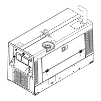
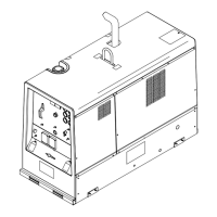
Illustrates and lists parts for the main assembly of the unit.
Shows and lists components of the control box for CC models.
Illustrates and lists parts for the CC/CV models' control box assembly.
Details components on the front panel for CC models.
Lists and illustrates components on the front panel for CC/CV models.
Exploded view and parts list for the generator assembly.
Shows and lists parts for the main rectifier assembly.
Outlines the terms and conditions of Miller's limited warranty.
| Type | Engine-Driven Welding Generator |
|---|---|
| Welding Amperage Range | 30 - 300 A |
| Fuel Tank Capacity | 12 Gallons |
| Frequency | 60 Hz |
| Power Factor | 1.0 |
| Max Output | 300 A |
| Horsepower | 24.8 HP |
| Dimensions | Width: 25 in (635 mm) |
| Input Power | N/A (Engine-driven) |
| Generator Output | 10, 000 Watts Peak, 9, 000 Watts Continuous |
| Engine | Kubota D722, 3-cylinder diesel |
| Weight | 690 lb (313 kg) |