Do you have a question about the Miller TM-268 and is the answer not in the manual?
Explains symbols used throughout the manual to denote hazards and warnings.
Details various hazards encountered during unit servicing, including electrical, mechanical, and environmental risks.
Provides legally mandated warnings regarding chemicals known to cause birth defects or cancer.
Discusses electromagnetic fields generated by the welding circuit and potential interference with medical implants.
Defines specific safety symbols used in the manual, such as those for moving parts.
Explains various electrical and operational symbols, including circuit breakers, voltage, and current.
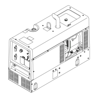
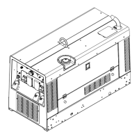
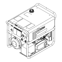
Provides a general overview of the belt-driven generator's function and components.
Lists technical specifications, dimensions, and output for the 4 kW generator models.
Lists technical specifications, dimensions, and output for the 7.5 kW generator models.
Illustrates the relationship between voltage and current for the generator models under different conditions.
Outlines recommended maintenance tasks and intervals for the generator unit.
Explains the overload protection mechanism, typically a circuit breaker, for the generator.
A guide to identify common generator problems and their solutions for 4 kW models.
Procedures for re-establishing the generator's magnetic field when output is lost.
A guide to identify common generator problems and their solutions for 7.5 kW models.
Provides a detailed circuit diagram for diagnosing issues in the 7.5 kW generator.
Displays expected output waveforms for proper generator operation and troubleshooting.
Instructions and guidance for testing the Power Board PC1 component.
Lists specific voltage and signal values to check on the Power Board PC1 for diagnostics.
Instructions and guidance for testing the Control Board PC2 component.
Lists specific voltage and signal values to check on the Control Board PC2 for diagnostics.
Describes the process for inspecting, replacing, and cleaning generator brushes and slip rings.
Instructions for configuring the Control Board PC2 for 50 Hz frequency operation.
Procedures for verifying generator output and performing post-service checks.
Step-by-step guide for taking apart and putting back together the 4 kW generator.
Step-by-step guide for taking apart and putting back together the 7.5 kW generator.
| Starting System | Recoil Start |
|---|---|
| Noise Level | 68 dB |
| AC Output | 120V |
| DC Output | 12V, 8.3A |
| Engine | OHV 4-Stroke |