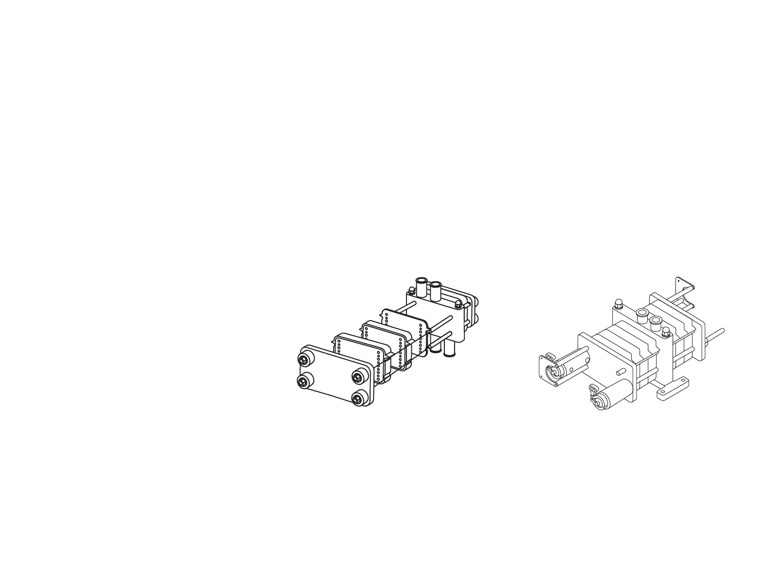
Pellicon
®
3 Cassettes Installation and User Guide 5
5. Slide the Pellicon
®
3 cassette up against the manifold adapter plate. The dark
grey center with light grey perimeter of the manifold adapter plate should be up
against the Pellicon
®
3 cassette.
6. Replace the spacers, washers and nuts as shown in Figure 5. Hand-tighten the
nuts in a diagonal fashion (see Figure 4). Use a few drops of suitable lubricant on
the tie-rods and between the nuts and the washers if required.
Note Uneven tightening of the nuts can damage the Pellicon
®
3 Cassette.
Nonparallel plates or compression of the filters at one end can cause leakage.
7. Tighten the nuts using the torque wrench and 15/16 in. deep hex socket supplied
with the Pellicon
®
3 Cassette Holder.
8. Set the torque wrench by turning the knurled locking collar clockwise or by pulling
the handle out to unlock. Turn the torque setting scale clockwise until the 350 in-lb
(40 Nm) mark on the torque scale is opposite the zero mark on the smooth collar.
Turn the knurled locking collar counterclockwise to lock.
9. Using the torque wrench and 15/16
in. deep hex socket, turn each nut
1/8 turn in the sequence shown in
Figure 4. When the wrench clicks,
this indicates that the set force
has been reached. DO NOT OVER
TORQUE. Evenness of torque is
critical to system performance.
Note Depending on the results of the
Integrity Test, the torque may need
to be increased at intervals of 50
in-lb (5.6 Nm) up to a maximum of
550 in-lb (62 Nm).
10. Recheck the torque prior to use.
Process Scale Holder
Hydraulic Process Scale Holder
Hydraulic Process Scale
Holder Installation
The Hydraulic Closure with Manual
Controls is intended for use with the
Millipore Process Scale Filter Holder. It
will maintain appropriate pressure on
the holder during processing or during
storage of installed filter cassettes.
RUN mode is required for process
operations. The system hydraulic pressure
is maintained at 1800 psig ± 100 psig.
In STORE mode, the system may be
stored with the Pellicon
®
3 cassettes
installed. The system hydraulic pressure
is maintained at 1200 psig ± 100 psig.
1. Set the System Mode switch to DUMP.
Note
Check the Hydraulic Pressure Gauge
on the hydraulic power unit panel to be
sure the pressure is relieved. Do not
proceed until the hydraulic pressure
reaches 0 psig as read on gauge PI-2.



 To Next Page