Do you have a question about the Millipore WP6111560 and is the answer not in the manual?
Step-by-step guide for replacing the pump's diaphragm and liner.
Instructions for removing and replacing the O-ring gasket in the pump head.
Identifies causes and solutions for poor vacuum issues in the pump system.
Details common causes and fixes for problems related to pump pressure.
Information on available part kits and recommended repair procedures.
Technical details including performance, dimensions, materials, and environmental conditions.
Catalogue numbers and ordering details for pumps and replacement parts.
Includes notice, contact info, technical assistance, and warranty details.
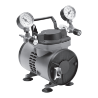
The Chemical Duty Vacuum/Pressure Pump is a continuously running, constant air flow unit designed for use with laboratory equipment. It operates by compressing air using a long-life diaphragm, which flexes within the compressor, providing the uniform operation characteristic of diaphragm-type pumps. This pump is suitable for various applications, including the filtration of liquids or gases, and other continuous or intermittent laboratory uses with all types of filter holders.
The pump is engineered to provide both vacuum and pressure capabilities. It features a pump head, a vacuum gauge, and a pressure gauge to monitor and control the desired vacuum or pressure levels. The unit is equipped with a vacuum valve and a pressure valve, allowing users to adjust the output precisely. An on/off switch located on the front of the pump controls its operation.
For vacuum applications, the vacuum is adjusted by closing the pressure regulator and fully opening the vacuum regulator (counterclockwise). The vacuum regulator is then slowly tightened clockwise until the desired vacuum reading is achieved on the vacuum gauge. Conversely, for pressure applications, the pressure is adjusted by turning the vacuum regulator fully down and opening the pressure fully (counterclockwise). The pressure regulator is then slowly tightened clockwise until the desired pressure reading is obtained on the pressure gauge.
Safety is a paramount consideration in the design and recommended usage of this pump. It is crucial to always use the supplied hydrophobic vent filter or a vacuum-flask water trap in conjunction with the pump to prevent liquids or vapors from entering and damaging it. The pump should never be used to pump or draw liquids directly. For maximum protection against vapors and gases, using both the Millex®-FA50 vent filter and a vacuum trap is recommended. The filter flask and vacuum trap should be emptied after each use.
The pump is designed for indoor use in a dry, clean, and well-ventilated area. To ensure proper cooling and prevent overheating, the pump's cooling fan must not be blocked and should be positioned at least 1 inch (2.5 cm) away from any wall or obstruction. The unit rests on four vibration isolator pads, which help minimize operating noise.
Before operation, users should unpack the unit and retain all packing material until proper product operation is verified. The pump should be placed on a suitable surface, such as a bench, desk, or table, ensuring that ventilation holes on the motor housing are not blocked. Appropriately sized tubing, typically 1/4 inch I.D., should be selected to withstand the anticipated pressure or vacuum.
When setting up, prepare the necessary equipment or filter holder and connect the tubing to the equipment first, but do not connect the tubing to the pump yet. After plugging the power cord into an appropriate electrical source, turn on the pump using the toggle switch. Only after the pump is operating should the tubing be connected from the filter holder or other equipment to the pump. If the pump is inadvertently turned on with the tubing fully connected and does not run, it should be turned off, the tubing disconnected, and then restarted. If the thermal overload switch activates, disconnect the tubing and allow the pump to cool for at least 10 minutes before restarting.
The pump is supplied with a Millex®-FA50 hydrophobic vent filter and 27 inches (69 cm) of 1/4 inch (6 mm) I.D. silicone vacuum tubing. The motor and pump are permanently lubricated, and a thermal overload switch with automatic reset protects the motor. All internal surfaces, except the stainless steel leaf valves, are coated with PTFE polymer to prevent corrosion, and the diaphragm is PTFE-lined to resist attack by chemicals or solvent vapors.
The chemical duty vacuum/pressure pump is designed for many hours of trouble-free operation under normal conditions and with proper handling. It is a 100% oil-free dry vacuum/pressure pump, employing a non-lube piston and cylinder. The bearings are sealed and permanently lubricated, requiring no maintenance or lubrication attempts. The units are built for continuous duty operation, emphasizing quietness and durability.
It is critical not to lubricate any parts with oil, grease, or petroleum products, as this can lead to polluted air delivery and damage the pump. Cleaning should not be done with acids, caustics, or chlorinated solvents. The connecting rod or motor bearings should not be replaced.
Before performing any maintenance, the pump must be disconnected from the power source.
Regular maintenance includes replacing the Millex®-FA50 vent filter (SLFA05010) when necessary. The pump system must be thoroughly clean to operate at maximum efficiency.
For diaphragm replacement:
For O-ring replacement:
In case of troubleshooting, issues like low flow, low pressure, the unit not starting, motor overheating, or loud operation can be addressed. Common causes include damaged valves, debris in valves, worn diaphragm, loose head screws, bent motor shaft, loose fittings, insufficient ventilation, loose rod clamping screw, and damaged O-rings. Corrective actions range from replacing flapper valves, removing debris, replacing the diaphragm and/or liner, tightening screws, replacing the entire unit, increasing air circulation, applying Loctite® 242, and replacing O-rings.
Two replacement part kits are available: a Pump Maintenance Kit (WP61MNT00) and a Pump Rebuild Kit (WP61RBD00). The maintenance kit includes a diaphragm, diaphragm liner, O-ring gasket, head screws, and handle screws. The rebuild kit includes a hold-down plate assembly, valve plate assembly, pump head, vacuum gauge, pressure gauge, head screws, and handle screws. It is recommended that trained service technicians perform repairs.
| voltage | 115 V~, 60 Hz |
|---|---|
| current | 3.5 A |
| motor power | 1/15 HP |
| temperature range | 5 °C (41 °F) to 40 °C (104 °F) |
|---|---|
| relative humidity | 80% for temperatures up to 31 °C, Max. decreasing to 50% at 40 °C |
| altitude | Max. 2, 000 meters |
| length | 7.5 in. (19.1 cm) |
|---|---|
| width | 7 in. (17.8 cm) |
| height | 8 in. (20.3 cm) |
| weight | 9 lbs (4.1 kg) |
| voltage | 100 V~, 50/60 Hz |
|---|---|
| current | 4.0 A |
| motor power | 1/15 HP |
| temperature range | 5 °C (41 °F) to 40 °C (104 °F) |
|---|---|
| relative humidity | 80% for temperatures up to 31 °C, Max. decreasing to 50% at 40 °C |
| altitude | Max. 2, 000 meters |
| length | 7.5 in. (19.1 cm) |
|---|---|
| width | 7 in. (17.8 cm) |
| height | 8 in. (20.3 cm) |
| weight | 9 lbs (4.1 kg) |
| voltage | 230 V~, 50 Hz |
|---|---|
| current | 1.7/1.1 A (Schuko) plug |
| motor power | 1/15 HP |
| temperature range | 5 °C (41 °F) to 40 °C (104 °F) |
|---|---|
| relative humidity | 80% for temperatures up to 31 °C, Max. decreasing to 50% at 40 °C |
| altitude | Max. 2, 000 meters |
| length | 10.5 in. (26.7 cm) |
|---|---|
| width | 9.4 in. (23.9 cm) |
| height | 9.7 in. (24.6 cm) |
| weight | 12 lbs (5.4 kg) |