Do you have a question about the Milltronics VM20 and is the answer not in the manual?
Explains DANGER, WARNING, and CAUTION safety alert symbols.
Essential safety checks before operating the machine.
Fundamental safety rules and electrical hazards.
Safety precautions for attire, hair, and personal protection.
Safety guidelines for machining operations and tooling use.
Safety precautions for performing maintenance tasks on the machine.
Rules and hazards related to electrical systems.
Table of physical and performance specs for VM models.
Diagrams and dimensions for VM22, VM25, VM30 models.
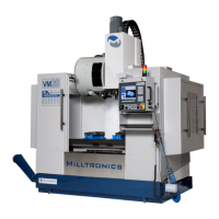
Diagrams and dimensions for VM15, VM16, VM20 models.
Guidelines for selecting a suitable location for the machine.
Essential electrical power and grounding specifications.
Instructions and warnings for transformer connection.
Requirements and adjustments for the air supply system.
Procedure for leveling and tramming the machine.
Verifying the functionality of the E-Stop button.
Daily run-in procedure for the machine spindle.
Procedures for clearing electrical faults by cycling power.
Guidelines for periodic maintenance and safety system checks.
Overview of the front panel controls and display.
Disabling machine motion and drives.
| Type | Vertical Machining Center |
|---|---|
| Table Size | 47.2 in x 23.6 in |
| X-Axis Travel | 40 in |
| Spindle Speed | 8, 000 rpm |
| Spindle Motor | 20 hp |
| Weight | 12, 125 lbs |
| Control | Centurion 7 |
| Y-Axis Travel | 20 in |
| Z-Axis Travel | 20 in |
| Tool Capacity | 20 |