Do you have a question about the Milnor 42044 WR2 and is the answer not in the manual?
Instruction to consult the separate safety manual before operation.
Lists components for various control box layouts.
Details various printed circuit boards used in the system.
Details Milnor's standard warranty coverage, exclusions, and limitations.
Instructions on how to identify and order necessary repair parts.
Explains component prefixes and their meanings in schematic diagrams.
Illustrates and explains symbols for relays and photo-eyes.
Defines symbols for buzzers, clutches, displays, fuses, and lights.
Explains symbols for transformers, motors, and variable speed inverters.
Illustrates symbols for various switch types like cam, hand-operated, and key lock.
Explains symbols for terminal boards and rectifiers (ZF).
Shows pin locations for AMP and Molex connectors.
Illustrates different types of plug-in relays and their pin configurations.
Detailed pin numbering for 36-pin and 18-pin AMP connectors.
Detailed pin numbering for various Molex connector sizes.
Illustrates symbols for pressure, toggle, and rotary switches.
Explains how to read schematic diagrams, including line numbers and match points.
Diagram showing component layout and connections for autospot.
Explains wire marking and details of the 3-wire circuit.
Illustrates wiring for three-phase single-speed motors with multiple voltage ratings.
Provides various single-speed motor connection diagrams based on lead configurations.
Details inputs and outputs for MILTOUCH-EX controls on WR2/3 models.
Instructions for testing and adjusting ESPS and ESPS2 power supply voltages.
Diagram of board connections and layout for 42044WR2/3 low voltage box.
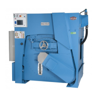
Shows component placement within the 42044 WR2/SR2 high voltage control box.
Shows component placement within the 60044WR2/3 high voltage control box.
Diagram of board connections for the 60044WR2/3 low voltage control box.
Diagram showing board connections for the 72044WR2/3 low voltage control box.
Shows component placement within the 7244WR2/3-7244SR2/3 high voltage control box.
Wiring diagram for microprocessor inputs related to autospot pockets.
Diagram showing connections for autospot sensors like ELPS.
Illustrates logic for autospot switches (SCAS) and relays (CRAS).
Details the start circuit and jog logic for 72044WR2/3 autospot.
Wiring diagram for microprocessor inputs related to autospot pockets.
Diagram showing connections for autospot sensors and relays on 60044 WR2/3.
Shows wiring between power supplies and various control boards.
Illustrates wiring for temperature probe and flow meter to control boards.
Diagram showing relay and valve connections for chemical flush operations.
Details the wiring for chemical flush valves (VEC06-VEC14).
Shows connections for interpret relays used in chemical pump control.
Illustrates how interpret relays control chemical pumps.
Diagram showing valve connections for central liquid supply flush system.
Wiring for flush manifold valves (VEC15, VECFM).
Shows valve control circuits for brake, hot/cold water, and drain functions.
Diagrams for drain-to-reuse and cooldown valves.
Illustrates valve controls for brake, water, and drain-to-sewer functions.
Shows microprocessor inputs related to speed, brake, and clutch controls.
Details various input signals to the microprocessor for system control.
Illustrates contactor circuits for drain, wash, and autospot motors.
Shows wiring diagrams for low and high extract motors (MTE1, MTE2).
Illustrates wiring for drain, wash, and autospot motors (MTDR, MTWA, MTAS).
Shows transformer wiring for 200-240VAC and 380-480VAC control circuits.
Illustrates the transformer wiring for 600VAC control circuit power.
Shows logic for door latch switches and the master switch.
Provides notes on jumper usage for autospot and 2-door models.
Illustrates door latch and 3-wire control logic with associated relays.
Shows connections for speed switches and clutch control.
Details logic for door latch and 3-wire circuits with various switches.
Illustrates inverter wiring for autospot and jog control functions.
Shows inverter and motor connections, including braking unit.
Details inverter wiring for autospot, DC injection, and alt extract.