R
Pellerin Milnor CorporationPellerin Milnor Corporation
P. O. Box 400, Kenner, LA 70063-0400
Litho in U.S.A.
BMP920025/92662V (1 of 2)
BMP920025/92662V
(Sheet 1 of 2)
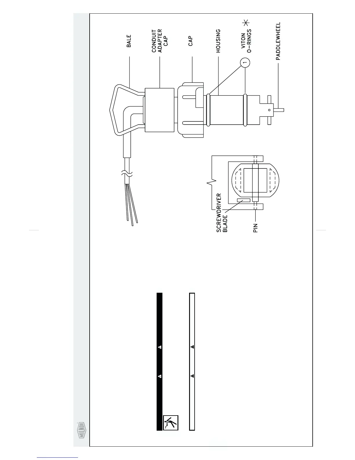
Paddlewheel Flow Sensor
Identification and Description
The flow sensor is installed in a pipe line to measure flow rate. The flow passing by the flow sensor
paddlewheel rotates the paddlewheel, moving the magnets past a coil in the transducer body. An AC
voltage is induced in the coil by the rotating magnets of the paddlewheel.
Both frequency and amplitude of the output of the coil are directly proportional to the velocity of
the fluid flow in the pipe. A complete cycle occurs every time two of the paddlewheel blades go by the
coil; therefore, two entire cycles are generated for each paddlewheel rotation.
Safety Instructions
Lock OFF and tag out power to machine at wall disconnect. Power
switches on machine and control box disable only control circuit power in
electrical boxes.
DANGER
SHOCK HAZARD will cause death or severe injury.
+
CAUTION
+
Turn off fluids before removing flow sensor from pipe line.
+
Maintenance
1
2
3
. Paddlewheel must turn freely, if not, see troubleshooting below.
. Inspect flow sensor electrical connections and cable.
. Check O-rings and lubricate with G.E. Silcone Compound G660 or similar. Keep paddlewheel
and pin free of lubrication (replacement paddlewheels and other parts are available from
manufactuer).
Troubleshooting
The flow sensor requires minimal care. Check your flow sensor every three months until actual
maintenance intervals can be determined. After removing flow sensor:
1
2
3
. Remove the flow sensor from the pipe and insert the plug into the pipe fitting. Clean any external
debris from the paddlewheel.
. Using a small flat-bladed screwdriver, gently pry one of the paddlewheel mounting ears away
from the pin (see FIGURE 2).
. When one end of the pin is free, gently work the paddlewheel and pin out of the remaining mount-
ing ear.
4. Throughly clean the pin, paddle, and pin holes with a wire brush and/or toothpick along with al-
cohol and/or soap and water.
5. To reinstall the paddlewheel and pin, reverse steps 1, 2, and 3.
6. After cleaning, the paddlewheel should spin freely without binding or sticking.
The paddlewheel is designed to rotate on the shaft; the shaft should not rotate with respect to the
housing. The paddlewheel must turn freely. If it does not, clean the paddlewheel assembly as follows:
FIGURE 2: REMOVAL OF
PADDLEWHEEL PIN
FIGURE 1: FLOW SENSOR
F
 Loading...