ÏTable B—Main Drive Belt Tension Specifications
Model Cycle Belt Deflection
inches (millimeters)
Initial Tension
pounds (kilograms)
Final Tension
pounds (kilograms)
30015, 30018, 30020, and 30022
(Single motor drive)
All 15/64 (5.9) 5.1-6.6 (2.5-3.0) 3.9-5.1 (1.7-2.5)
30015 (Dual motor drive) All 1/4 (6.35) 5.1-6.6 (2.5-3.0) 3.9-5.1 (1.7-2.5)
30020 and 30022
(Dual motor drive)
50 15/64 (5.9) 4.3-5.6 (1.9-2.7) 3.3-4.3 (1.2-1.8)
60 15/64 (5.9) 5.1-6.6 (2.5-3.0) 3.9-5.1 (1.7-2.5)
ÊRemoving Pulleys
Replace the pulleys if the side walls are chipped, broken, or excessively worn. Remove the console top and
belt guards, then remove the appropriate belts, dirt, or paint from the shaft end. Determine the type of pulley to be
removed and see the appropriate instructions below.
ËStraight Bore Pulleys
1. Loosen set screws at the bottom of the pulley groove and remove the pulley. Retaining compound was used
during factory installation; it may be necessary to heat the shaft while applying pressure with a puller.
2. Determine that the shaft and inside bore are dry and free of dirt, burrs, and old adhesives.
3. Place the key in the shaft and pulley to check key fit. Key must fit snugly, if not, replace the key or pulley.
4. Apply retaining compound (Loctite 609) to the pulley bore and shaft, being careful not to over-apply. Turn
the pulley back and forth while installing to evenly distribute Loctite. Align the pulley with the correspond-
ing pulley (see “Aligning Pulleys” in this section) and wipe off any excess Loctite.
5. Tighten the set screws. Always use new set screws. To adjust the belt tension, see “Testing Belt Tension” in
this section. Allow Loctite to cure for six hours before placing the machine in service.
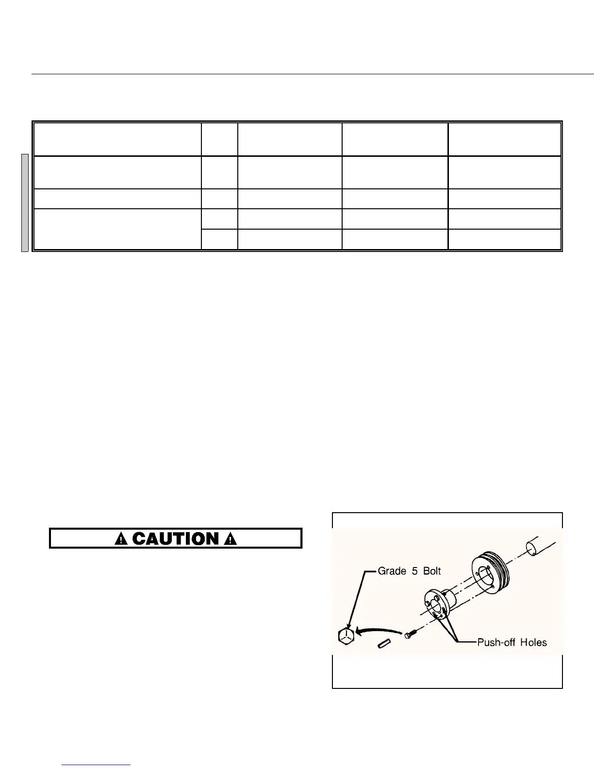
ËTaper Lock Bushing Pulleys
DO NOT use lubricants, “Loctite” or other
compounds on taper lock bushings, pulleys,
or shafts.
1. Loosen and remove all three bushing screws. Thread two
screws into the push-off holes in the bushing (FIGURE 4)
and alternately tighten them until the bushing and pulley
separate and can be removed from the shaft.
2. Remove the burrs from the shaft, then clean and polish
shaft. Clean tapered surfaces of bushing and inside bore of
pulley. Determine that inside bore of bushing is clean and
clear.
3. Place the key in shaft. Check for a proper fit. Key must fit snugly; if not, replace the key or bushing.
4. Insert the bushing loosely into the pulley and start all three screws. Install the pulley on the shaft and approxi-
mately align it with the corresponding pulley.
5. Gradually tighten the grade 5 bolts in an alternating pattern until the bushing is seated within the pulley (use
the “Initial Torque” in Table C below). Rotate the pulley and check for wobble or runout.
6. Install the belt(s), adjust out all slack, and align the pulleys (see “Aligning Pulleys” in this section).
7. Tighten the bushing bolts to the “Final Torque” value in Table C below, and adjust the belt tension according
to “Testing Belt Tension” in this section.
ÏTable C—Bushing Bolt Torque Specifications
Size Code
(Stamped on bushing)
Bolt Size Initial Torque
inch pounds
(kilogram/meters)
Final Torque
inch pounds
(kilogram/meters)
H or SD (30015)
(Dual motor drive)
1/4" x 20 54 (.62) 108 (1.24)
P1 (30020 and 30022)
(Dual motor drive)
5/16" x 18 96 (1.10) 190 (2.18)
SD
(All single motor drive)
1/4" x 20 54 (.62) 110 (1.26)
ËElectric Clutch Pulleys
—Do not use a pulling tool to remove the clutch. Remove the clutch by removing
the center mounting bolt and gently tapping the clutch off.
ÊAligning Pulleys
After replacing the drive train components, check the
pulley alignment according to FIGURE 5.
ËWash and Drain Belt Pulleys
(Dual motor machines only)
1. Stretch a string from the wash clutch on the jackshaft to
the rear pulley on E2/Drain (large) motor. Position the
string similar to FIGURE 5, but with the string touching
the pulley faces on the motor side.
2. Adjust E2 motor and/or rear pulley position, until the
string touches points A, B, C, and D. Secure E2 motor
and/or rear pulley. Now check the pulley on the E1/Wash
(small) motor for alignment with E2 motor pulley.
3. Stretch a string from E1 motor pulley to E2 motor pulley.
Adjust E1 motor and/or pulley position until the string
touches A, B, C, and D. Secure E1 motor and/or pulley.
ÎFIGURE 4
(MSSM0706BE)
ÎTaper Lock Bushing
ÎFIGURE 5
(MSSM0706BE)
ÎAligning Pulleys
C
C
B
 Loading...