MSSM0711AE/9272BV
ÈREPLACING AND ADJUSTING
THE POWER SUPPLY
In the unlikely event of a power supply failure, see the
replacement and adjustment instructions for the machine in
this section. Use a high quality digital voltmeter (Fluke model
77 or similar) for measuring voltages.
ÊFor C4A, M4A, System 7
®
,
and E-P Plus
®
Models
ELECTROCUTION HAZARD—
High voltage is present inside
electric boxes, motors, and many
other components. Power switch-
es on machine disable only control circuit
power in certain boxes. You can be killed or
seriously injured on contact with high voltage.
☞ Lock OFF and tag out power at the wall
disconnect before servicing.
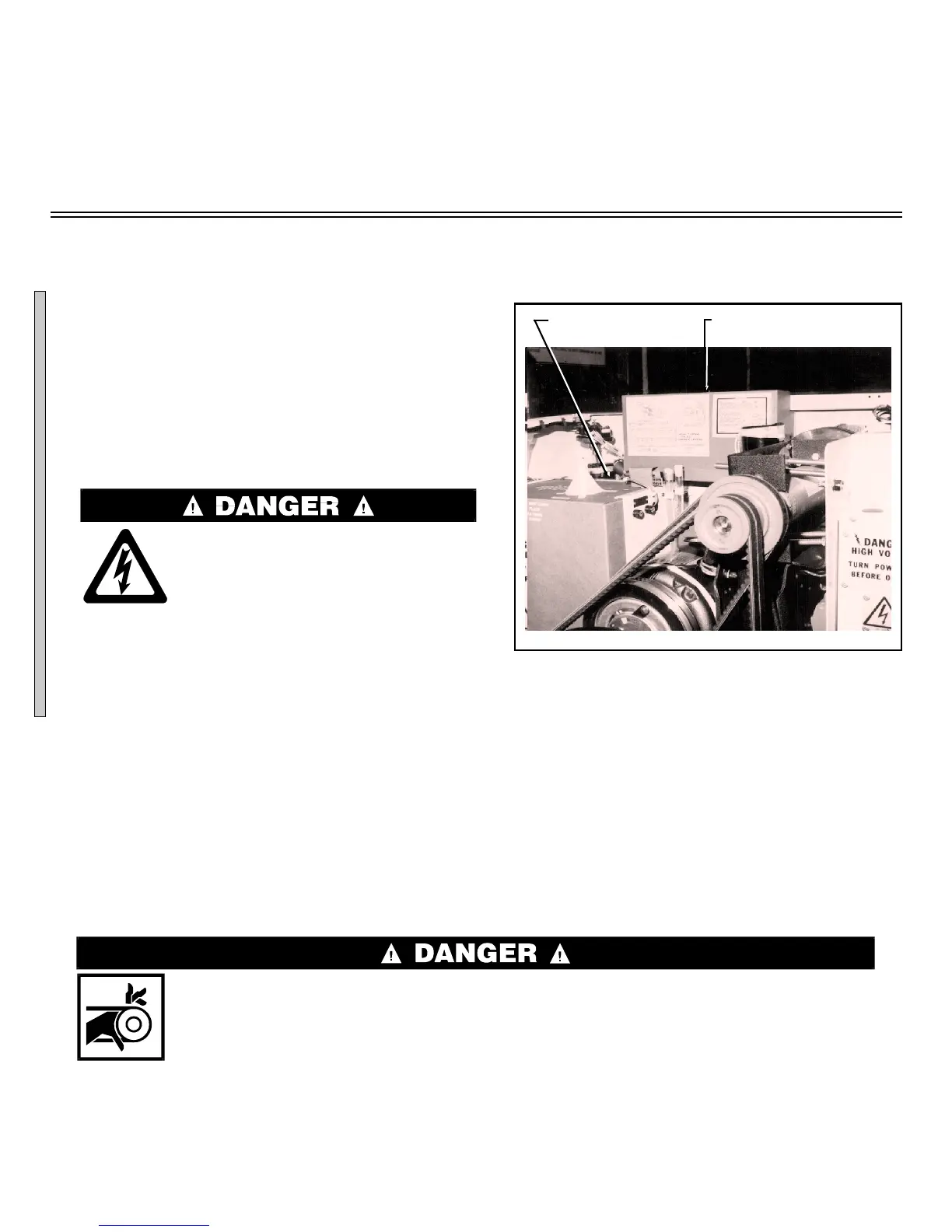
ËReplacing the Power Supply
—See FIGURE 1 during the following procedures:
1. Remove the console top and belt guard.
2. Remove the power supply and processor board covers.
3. After replacing the power supply, see “Adjusting Output Voltage” in this section.
ËAdjusting Output Voltage
CRUSH AND ENTANGLE HAZARD—Machine power is ON and covers are re-
moved for the following procedures. Rotating machinery can entangle and
crush body parts.
☞ Before turning power ON, open shell door to prevent machine rotation.
ELECTROCUTION HAZARD—Machine power is ON and covers are removed for
the following procedures. You can be killed or severely injured by contact with
exposed components which are energized at 120VAC or higher.
☞ DO NOT touch any components while adjusting output voltage.
See FIGURE 2 during the following procedures:
1. Restore power at the wall disconnect.
2. Locate connector MTA1 on the processor board. Touch the negative meter probe to the rear of pin 9
(ground connection).
3. Touch the positive meter probe to the rear of pin 3 (+5VDC).
Voltage must be between 4.95 and 5.06VDC. If not, turn the 5VDC potentiometer slowly (clockwise to
lower, counterclockwise to raise) until the meter displays the correct value. The microprocessor will not
operate if this voltage is not within tolerance. After setting 5VDC output voltage, with the negative meter
probe still touching the rear of pin 9 (ground connection):
1. Touch the positive meter
probe to the rear of pin 5.
The voltage must be between
+11.5 to +13.5VDC .
2. Touch the positive meter
probe to the rear of pin 7.
The voltage must be between
-11.5 to -13.5VDC.
Power Supply Cover Processor Board Cover
ÎFIGURE 1
(MSSM0711AE)
ÎLocation of Power Supply and
Processor Board ( E-P Plus
®
shown)
ÎFIGURE 2
(MSSM0711AE)
ÎLocation of Output Voltage Potentiometer and Connector MTA1
B

 Loading...