Service Connections
PELLERIN MILNOR CORPORATION
machine (never move L3 if L3 is a stinger leg). Never attempt to reconnect motors or the motor
control devices.
CAUTION 4 : Component Damage—Voltage fluctuations of more than 10% above or
below the specified voltage for your machine can damage electrical components, especially
motors.
• Any such conditions should be corrected prior to commissioning your machines.
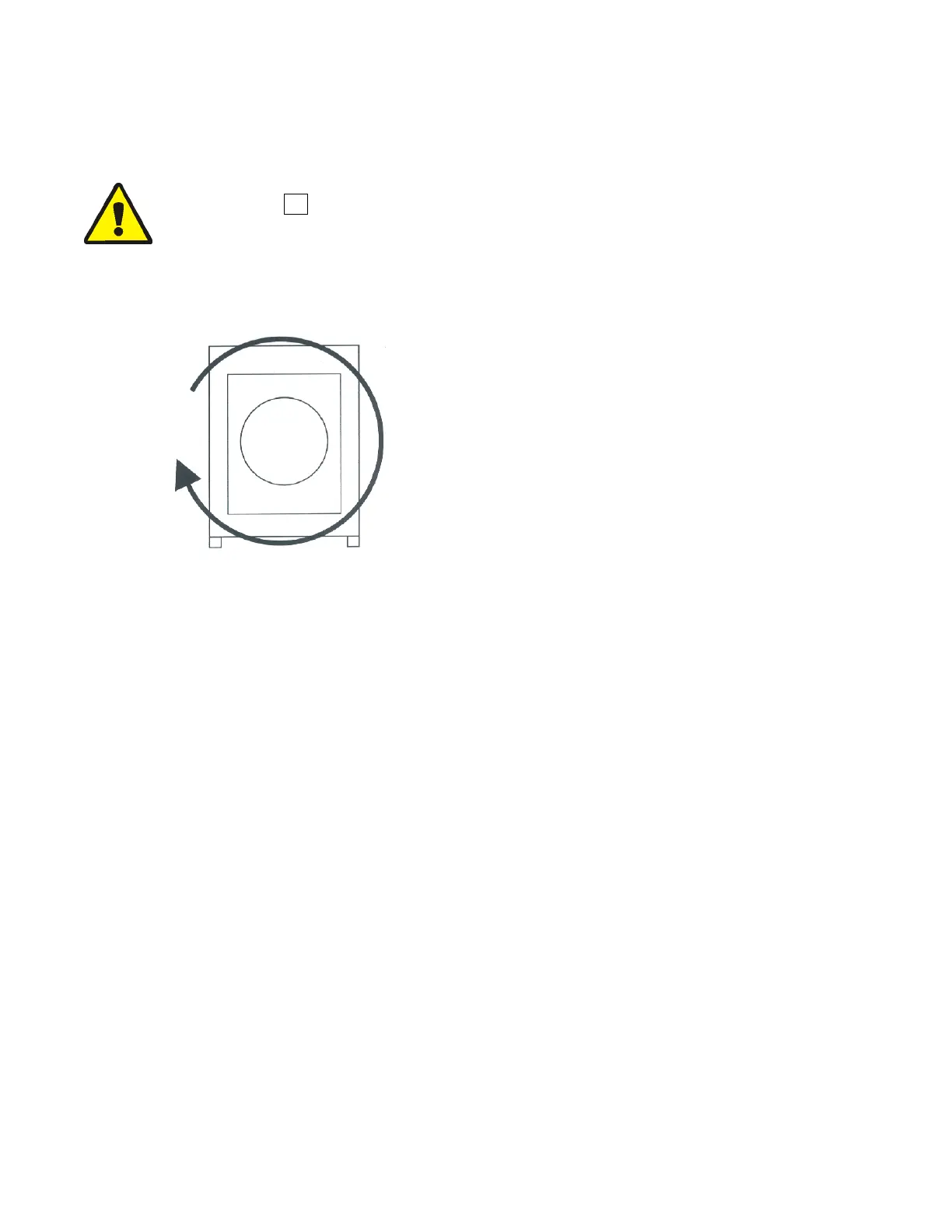
Figure 1: Rotation Direction
during Drain and Extract
Electric Power Connections—The customer must furnish a remotely mounted switch
with lag type fuses, circuit breakers and wiring between the electrical service box and the
junction box on the machine. The sizes of these fuses and wires, along with the motor fuses
supplied with the machine, depend on the machine voltage. See the fuse and wire sizing
information in the schematic manual and on the machine nameplate.
— End of BIIFUI01 —
51

 Loading...