Disk Brake Maintenance
PELLERIN MILNOR CORPORATION
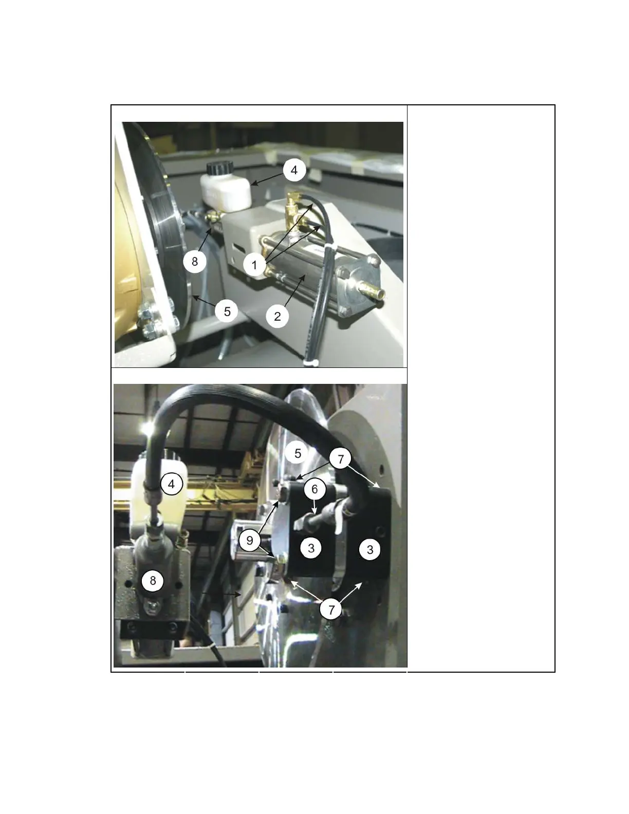
Figure 1: A typical hydraulic brake system
The air cylinder Legend
The hydraulic cylinder and the caliper
.
1. Tubing for air
2. Air cylinder
3. Caliper body halves
(Figure 2, item 2)
4. Hydraulic reservoir
5. Rotor disk
6. Hydraulic inlet
7. Valves to drain fluid and
bleed the brake
8. Hydraulic cylinder
9. Bolts to attach the caliper
(Figure 2, item 1)
1.
The Inspection of the Brake
Note 1: The brakes shown in this document can look different from your equipment.
Note 2: Do this inspection when the maintenance schedule tells it is necessary. Do this inspection after
you replace friction pads or do a caliper overhaul.
79

 Loading...