Disk Brake Maintenance
PELLERIN MILNOR CORPORATION
2. Turn the "brake release" output on. The air valve will supply compressed air to one of the
tubes. (Figure 1, item 1).
3. Quickly move one of the compressed air tubes (Figure 1, item 1) on and off the air cylinder.
4. After you complete this procedure, connect the air tubing.
6.4.
How the Brake Operates on Divided Cylinder Machines
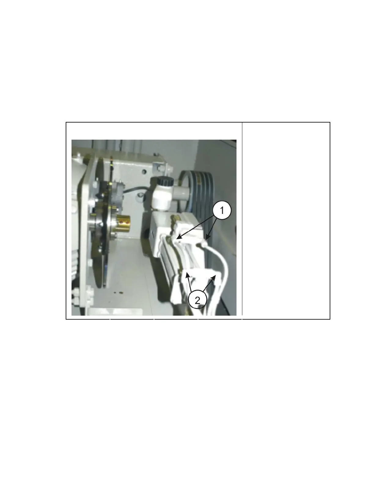
Figure 7: A Typical First and Second Brake on a Divided Cylinder Machine
Two pairs of air tubing connect to different ends of the air
cylinder.
Legend
.
1. Tubing for air that releases
the first brake ( 85 -100
PSI) ( 5.95 - 07.0 kg/cm-
cm)
2. Tubing for air that applies
the second brake (10 – 12
PSI) (0.7-0.84 kg/cm-
• On divided cylinder machines, two pair of air tubes connect to different ends of the air
cylinder.
• When the cylinder turns, air pressure at Figure 7, item 1 compresses the spring and releases
the brake.
• When you operate the stop control, air pressure at 1 is removed. Then the spring in the air
cylinder applies the brake.
• If you open the door, the 2nd brake is applied. Then the air pressure at Figure 7, item 2 and
the spring apply the brake.
6.5.
The Second Brake —If your machine has a second brake which uses air pressure and
spring pressure, it will have a pressure regulator. Make sure that you adjust the air pressure of the
second brake (Figure 7, item 2) to 10 – 12 PSI (0.7-0.84 kg/cm-cm).
— End of BIEUUM01 —
89

 Loading...