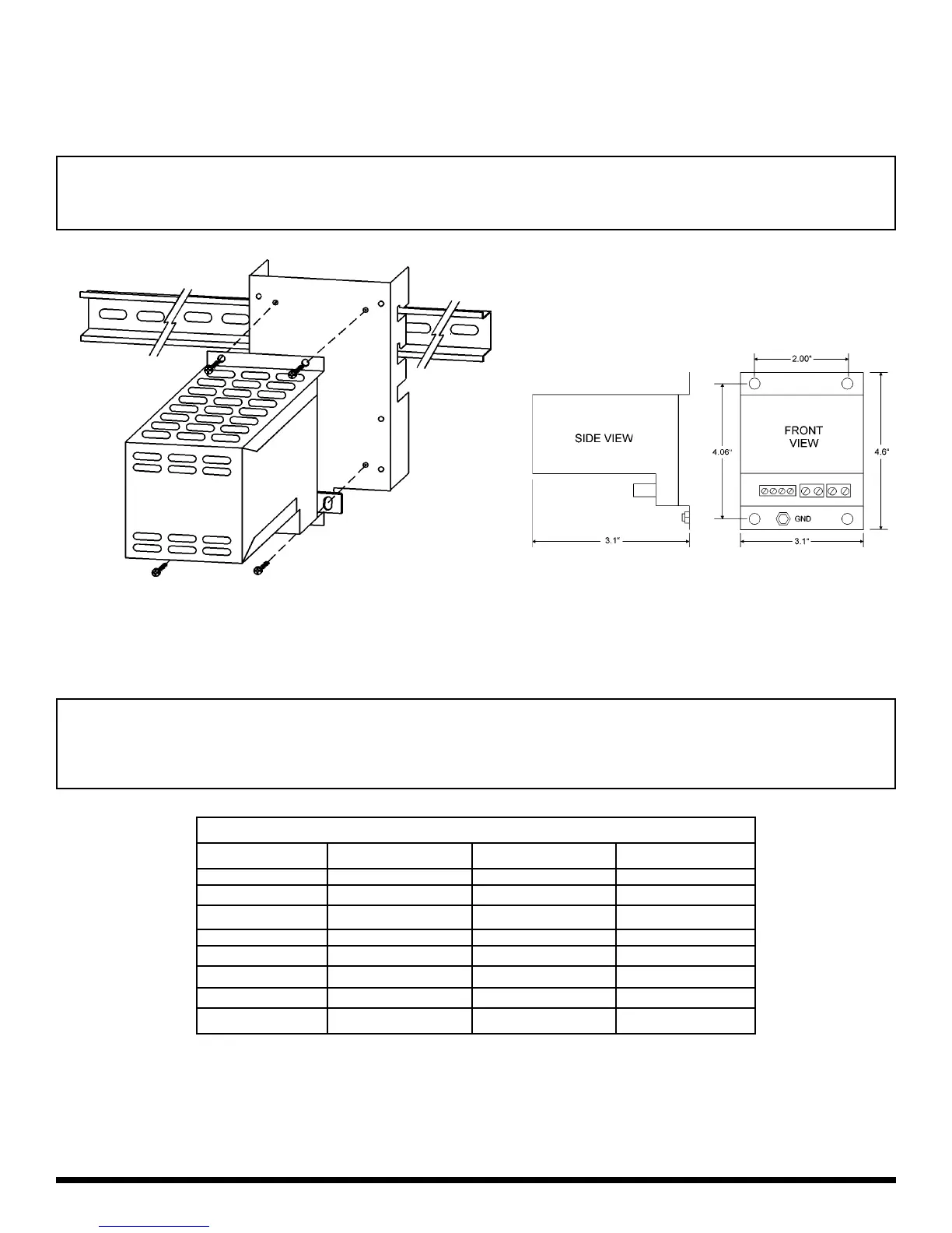
MOUNTING THE DYNAMIC BRAKING MODULE
The diagram below illustrates how to mount the DB Module. The DB Module is compatible with the DIN Rail Mounting Kit
option, or can simply be mounted to a flat surface such as an electrical panel.
SELECTING EXTERNAL RESISTORS
Use the chart below to select the proper external resistor assembly:
Minarik R 901 E. Thompson Ave. R Glendale, CA 91201 R Ph: (800)646-2745 R Fax: (800) 394-6334 R www.minarikcorp.com
NOTE: These resistor assemblies are the same as those used with the AC300 and AC400 Series drives. The DB Module does
not include short-circuit protection for the external resistors. If short-circuit protection is desired, fusing must be supplied by the
customer. Consult Minarik.
Warning
Hazard of electric shock! External resistors are connected to the drive’s DC bus, which can read 950 VDC. Connections to
external resistors must be electrically insulated and mechanically shielded for safety. High Voltage warning signs are also
recommended.
Warning
DO NOT mount the resistors below the AC100 or AC200 Series drive! The resistors generate heat, and must be mounted above
or to the side of the drive.
EXTERNAL RESISTOR ASSEMBLIES
HP 240 / 200 Vac 480 / 400 Vac 590 / 480 Vac
0.25 - 0.5 841-100 841-101 N/A
1 - 1.5 841-101 841-101 841-100
2 841-102 841-102 841-101
3 841-104 841-104 841-103
5 841-105 841-105 841-104
7.5 - 10 841-106 841-106 841-107
15 - 20 841-108 841-108 841-109
25 N/A 841-110 841-111
 Loading...