SAMPLE WORKSHEET 3 (see page 14)
CT124 SETUP WORKSHEET
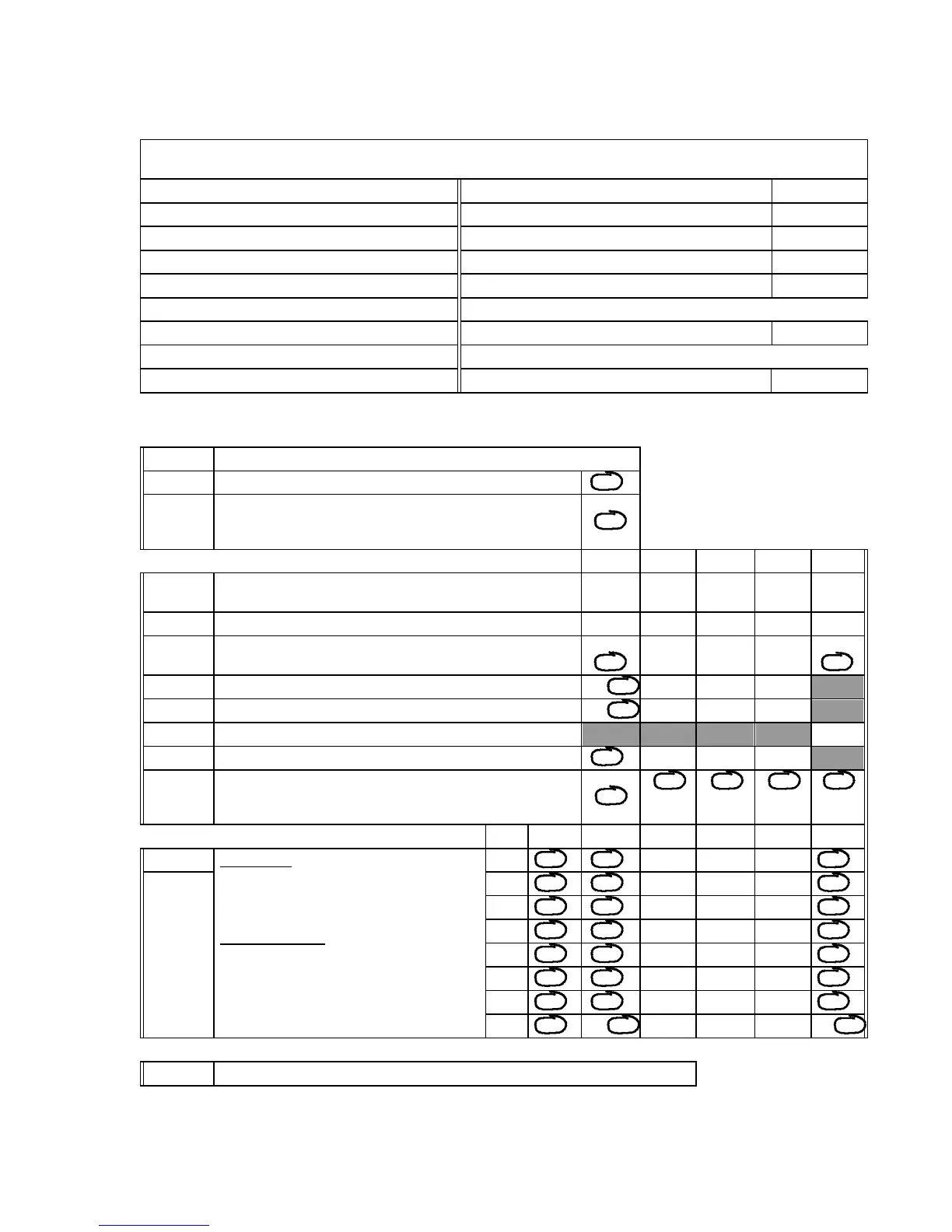
Use this worksheet to describe the setup parameters for the desired operation of the CT124.
Fill in a short description of the location and purpose of each temperature sensor, and save the worksheet for future reference.
Basic function description:
Monitor pipe temps, control auxiliary heater, frost alarm
Description of Zones Description of Relay Functions Trip Temp.
Zone 1: Pipe #1 Relay 1: Auxiliary heat control 38°F
Zone 2: Pipe #2 Relay 2: ---
Zone 3: Pipe #3 Relay 3: ---
Zone 4: Pipe #4 Relay 4: ---
Zone 5: Pipe #5
Zone 6: Pipe #6 Alarm only: Frost warning 35°F
Zone 7: Pipe #7
Zone 8: Room temp (monitor only) Completed by: BFJ Date: 9/87
Circle the option desired. If the box is empty, fill in a number within the range given at the left. If shaded, there is no option to choose.
DISPLAY
Code Description
dS Temperature scale °F, °C
dC Zone to be displayed during normal operation: Highest zone
Lowest zone
Any selected zone
HI
LO
AnY
OUTPUTS - RELAYS AND ALARM Relay 1 Relay 2 Relay 3 Relay 4 Alarm
rt or At Trip temperature: -40 to 482°F, -40 to 250°C (to 530°C or 986°F
with Platinum RTD) or "OFF" if the output will not be used
38 OFF OFF OFF 35
rH or AH Hysteresis (deadband): 2 to 20 °C or °F 4 2
rP or AP Trip on overtemperature (HI)
or undertemperature (LO)
HI
LO
HI
LO
HI
LO
HI
LO
HI
LO
rA Sound audible alarm when this relay trips? YES no YES no YES no YES no
rS Return this relay to normal when silence is pressed? YES no YES no YES no YES no
AS Length of alarm silence: 1 to 60 minutes, "---" for stays off. 30
rd or Ad Trip this output during diagnostic test? YES no YES no YES no YES no
ro or Ao Effect of override button on output: No effect
Trip
Untrip
no
On
OFF
no
On
OFF
no
On
OFF
no
On
OFF
no
OFF
INPUT ZONES Zone Scan Relay 1 Relay 2 Relay 3 Relay 4 Alarm
Sc. First Column:
Zones to be scanned:
YES = scanned
no = locked out
Remaining columns:
Outputs which respond to each zone:
YES = Output will trip on zone temperature
no = Output not tied to that zone
1 YES no YES no YES no YES no YES no YES no
r. or A.
2 YES no YES no YES no YES no YES no YES no
3 YES no YES no YES no YES no YES no YES no
4 YES no YES no YES no YES no YES no YES no
5 YES no YES no YES no YES no YES no YES no
6 YES no YES no YES no YES no YES no YES no
7 YES no YES no YES no YES no YES no YES no
8 YES no YES no YES no YES no YES no YES no
CALIBRATION
CAL. Press DONE unless you wish to recalibrate. See p. 20 of the Instruction Manual.
Minco Products, Inc. CT124 Instruction Manual
17
 Loading...