3. A 12 VDC electrical connection point must be made available near the placement of the DH-40 unit. An optional
quick connect plug MKR-12 is available for this connection when the unit is attached to a quick release plate.
4. The unit is designed to lift a 20lb.(min) to 40lb.(max) anchor.
5. The wiring from the battery to the unit must be 10 gauge minimum.
6. If the Davit and DH-40 are mounted more than 2 feet apart, the rope stop will need to be adjusted. Failure to do
so may cause the rope to completely unwind and rewind on to the spool backwards. This will cause the unit to
operate opposite the switch markings and will damage the gear system in the DH-40. Read the section
"Adjusting the Rope Stop" for instructions.
Note: Numbers in ( ) are item numbers referring to parts diagram.
WINCH AND DAVIT MOUNTED TOGETHER
1. Remove the DH-40 cover ( 47 ) by removing cover screws (49 & 53 )
2. Carefully place the DH-40 base on the deck of the boat near the bow.
3. Place the davit so the two rear holes line up with the two front holes of the DH-40 base. The rear of the davit lies
just inside and on top of the base.
4. Position the DH-40 and davit on the boat deck so the davit overhangs the boat edge by approxiamately 9".
5. The DH-40 base and the davit have been predrilled with the same mounting holes as were used on the DH-35.
They may be used when replacing a previous model or when applicable.
6. If mounting the DH-40 for the first time, mark the four
outer most holes in the base and the davit for drilling.
Keep in mind with this mounting method the davit and
base share the two middle holes.
3. Un point de raccordement électrique de 12 V de courant
continu peut être établi près du lieu de montage de l’unité
DH-40. Une prise à raccord rapide MKR-12 optionnelle
est disponible pour cette connexion quand l’unité est fixée
à la plaque à déblocage rapide.
4. L’unité et conçue pour soulever une ancre de 20 lb (min.) à 40 lb (max.).
5. Le câblage de la batterie à l’unité doit être composé de fil de calibre 10 au minimum.
6. Si le porte-manteau et le DH-40 sont montés séparés de plus de 60 cm (2 pi), l’arrêt de corde devra être réglé.
Omettre ceci peut faire que la corde se déroule complètement, puis s’enroule sur la bobine à l’envers. Ceci cau-
sera à l’unité de fonctionner dans le sens opposé à celui indiqué par l’interrupteur et d’endommager le système
d’engrenages dans le DH-40. Lisez la section intitulée « Réglage de l’arrêt de corde » au sujet des instructions.
Remarque : Les numéros entre ( ) sont des numéros d’article servant de référence entre la liste de pièces et le schéma.
TREUIL ET PORTE-MANTEAU MONTÉS ENSEMBLE
1. Enlevez le couvercle ( 47 ) du DH-40 en en retirant les vis ( 49 & 53 ).
2. Placez soigneusement le socle du DH-40 sur le pont du bateau près de la proue.
3. Placez le porte-manteau de façon à ce que les deux trous arrière s’alignent sur les deux trous avant du socle du
DH-40. L’arrière du porte-manteau repose à peine dans et sur le socle.
4.
Positionnez le DH-40 et le porte-manteau sur le pont du bateau de façon à ce que le porte-manteau dép
asse du
bord du bateau d’environ 23 cm (9 po).
5.
Le socle du DH-40 et le porte-manteau comportent les mêmes trous de mont
age que sur les et DH-35. Ces
trous peuvent être utilisés quand vous remplacez un modèle antérieur ou si cela s’applique.
6. Si vous montez le DH-40 pour la première fois, marquez les quatre trous les plus externes du socle et du porte-
manteau pour percer. Souvenez-vous qu’avec cette méthode de montage, le porte-manteau et le socle partagent
les deux trous du milieu.
22
25
21
18
26
29
56
58
24
23
19
20
55
54
53
52
9
14
13
10
57
11
12
48
38
37
39
46
51
50
49
47
17
16
30
27
31
32
33
34
36
12
11
40
41
42
43
44
45
15
13
8
7
6
5
4
3
2
1
59
66
64
65
67
60
61
62
63
23
35
70
69
68
14
3
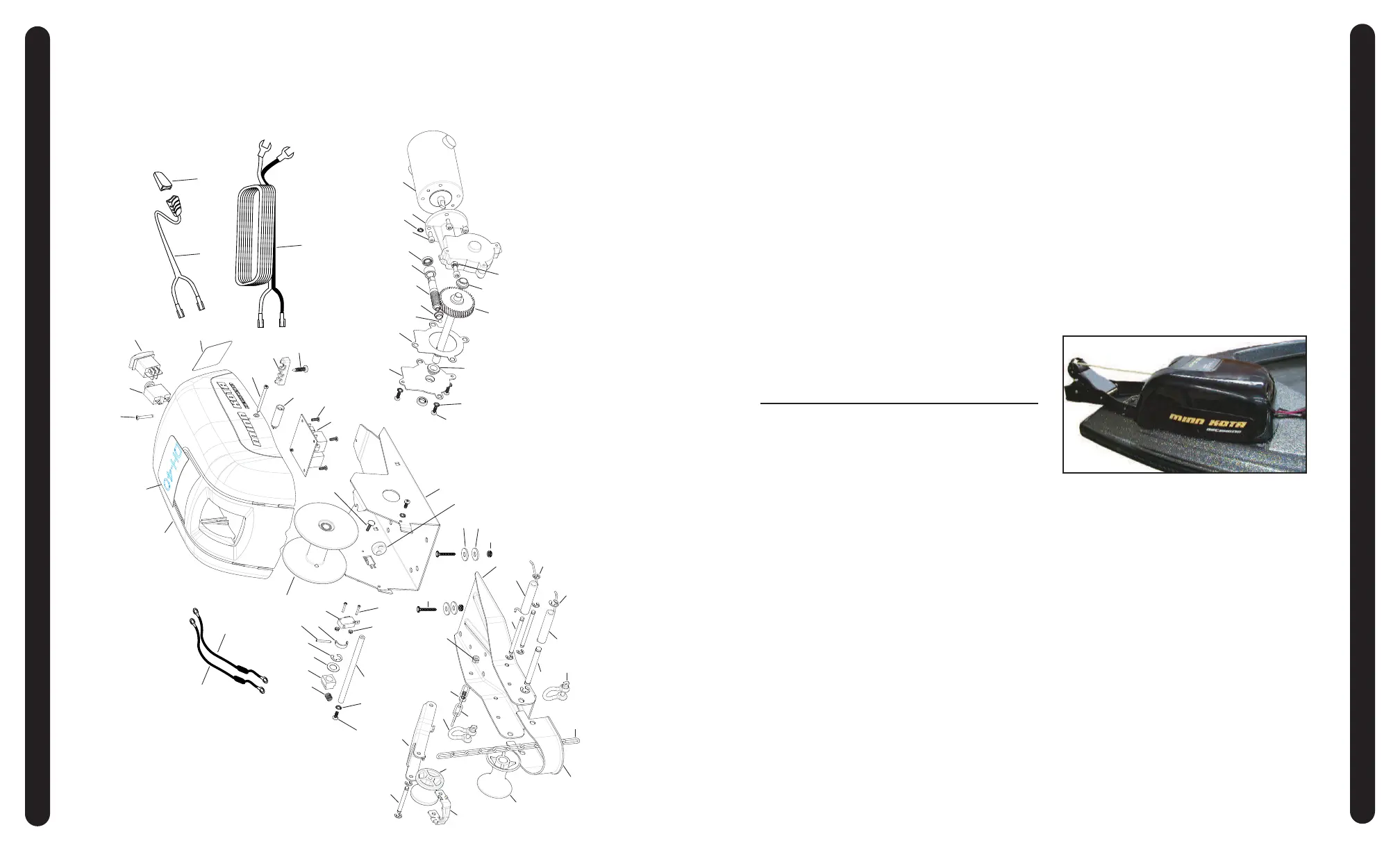
SCHEMATIC SCHÉMA
MOUNTING MONTAGE
This page provides MinnKota® WEEE compliance disassembly instructions. For more
information about where you should dispose of your waste equipment for recycling and
recovery and/or your European Union member state requirements, please contact your
dealer or distributor from which your product was purchased.
Tools required but not limited to: Flat Head screw driver, Phillips screw driver, Socket
set, Pliers, wire Cutters.
 Loading...