Do you have a question about the MINN KOTA TERROVA and is the answer not in the manual?
Information on registering your trolling motor and the importance of its serial number for identification and service.
Fields provided for the user to record motor model, serial number, purchase date, and store.
Warnings about safe operation, propeller hazards, user responsibility, and avoiding obstructions.
Notices regarding propeller safety, disconnecting power, and using approved accessories.
Details the two-year limited warranty on the entire product and lifetime warranty on the composite shaft.
Outlines warranty limitations, exclusions, and the process for obtaining service in the U.S.
Visual diagrams illustrating key parts of a boat, such as bow, stern, hull, and transom.
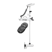
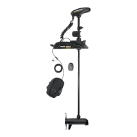
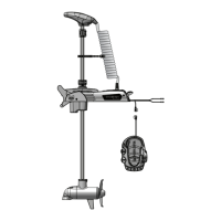
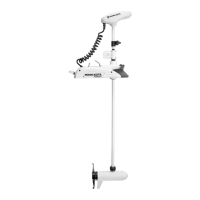
Description of features on the control head and mount, including AutoPilot and Stow Deploy Lever.
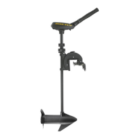
Details of components like the composite shaft, depth collar, and power motor.
Introduction to installing the Terrova, including a list of necessary parts for mounting.
Guidance on optimal mounting location and a list of required tools for installation.
Steps 1a and 1b: placing the mount and removing sideplate screws.
Steps for removing sideplates, positioning the base extrusion, and placing the motor.
Steps for checking mount levelness and drilling mounting holes using specified drill bit.
Steps for attaching the motor to the boat using screws, washers, and nuts.
Steps for replacing the sideplates to complete the mount assembly.
Steps for securing sideplate screws and installing foot pedal pads.
Guide to identifying cables for Built-In MEGA Down Imaging, Universal Sonar, and i-Pilot Link.
Basic guidelines for routing connection cables to prevent damage and interference.
Detailed steps for routing cables through the coil cord and to the mount.
Explanation of the Built-In MEGA Down Imaging feature and its capabilities.
Steps for connecting the Built-In MEGA Down Imaging cable to the control head.
Instructions for connecting the sonar system to Solix and Helix fish finders.
Information on Universal Sonar, including its 2D sonar capabilities and bonding wire.
Guidelines for routing the Universal Sonar cable and connecting it to the fish finder.
Steps for attaching and connecting a Universal Sonar extension cable if needed.
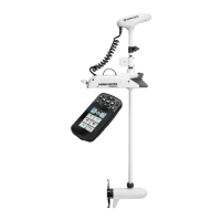
Overview of the i-Pilot Link system and its GPS capabilities.
Locating and identifying the 8-pin i-Pilot Link connector on the control head.
Steps for connecting the i-Pilot Link Ethernet cable to the fish finder or switch.
General recommendations for rigging your boat according to ABYC standards.
Table for selecting appropriate conductor gauge and circuit breaker based on wire length and amp draw.
Recommendations for battery types, maintenance, and ensuring battery life.
Advice on using alternator chargers and connecting accessories to trolling motor batteries.
Warnings about connecting jump start systems and selector switches to the trolling motor battery.
Procedure for connecting the motor to a 12-volt battery system.
Procedure for wiring two 12-volt batteries in series to provide 24 volts.
Procedure for wiring three 12-volt batteries in series to provide 36 volts.
Wiring diagram for Terrova models not factory-equipped with i-Pilot or i-Pilot Link.
Wiring diagram for Terrova models factory-equipped with i-Pilot or i-Pilot Link.
Description of various components of the motor mount, including the depth collar and stow lever.
Explanation of how to adjust the depth collar and operate the stow deploy lever.
Location and function of the power button on the indicator panel.
Details on the AutoPilot indicator light and the function of the Stow Deploy Lever.
Step-by-step instructions for safely deploying the trolling motor into the water.
Step-by-step instructions for safely stowing the trolling motor onto the boat.
Explanation of how to read the battery meter and interpret the LED indicators.
Detailed steps for adjusting the motor's depth for optimal performance.
Steps to ensure the lower unit is properly positioned and secured for safe transport.
Instructions for mounting and routing an external transducer cable.
General guide to operating the foot pedal for motor control.
How to adjust the motor's speed using the speed control knob.
How to engage and use the Spot-Lock feature for boat positioning.
Details on steering, prop on/off, and momentary operation controls.
Explanation of constant motor operation and how to use AutoPilot.
Step-by-step guide for removing and installing the trolling motor propeller.
Routine cleaning and care instructions for the motor and its components.
Solutions for common problems such as motor failure, power loss, and steering difficulty.
Resources for additional troubleshooting, parts purchasing, and service center locations.
Covers WEEE directive, product disposal, and regulatory compliance for i-Pilot equipped motors.
Details FCC, Industry Canada compliance rules, and environmental operating ratings.
Visual diagram illustrating the components of the Terrova control head.
List of individual parts and their corresponding part numbers for the Terrova control head.
Visual diagram illustrating the components of the 12 Volt Terrova motor.
Continuation of the visual diagram for the 12 Volt Terrova motor components.
List of individual parts and their corresponding part numbers for the 12 Volt motor.
Continuation of the parts list for the 12 Volt Terrova motor.
Visual diagram illustrating the components of the 24 Volt Terrova motor.
List of individual parts and their corresponding part numbers for the 24 Volt motor.
Continuation of the parts list for the 24 Volt Terrova motor.
Continuation of the parts list for the 24 Volt Terrova motor.
Visual diagram illustrating the components of the 36 Volt Terrova motor.
List of individual parts and their corresponding part numbers for the 36 Volt motor.
Continuation of the parts list for the 36 Volt Terrova motor.
Visual diagram illustrating the components of the Terrova steering housing.
List of individual parts and their corresponding part numbers for the steering housing.
Continuation of the parts list for the Terrova steering housing.
Visual diagram illustrating the components of the Terrova foot pedal.
List of individual parts and their corresponding part numbers for the foot pedal.
Visual diagram illustrating the components of the Terrova mount.
List of individual parts and their corresponding part numbers for the mount.
Continuation of the parts list for the Terrova mount.
Continuation of the parts list for the Terrova mount.
Information on recommended Minn Kota battery chargers for optimal battery care.
Details on the Talon shallow water anchor accessory, including its features.
List of other available accessories such as circuit breakers, brackets, and extension handles.
| i-Pilot GPS | Yes |
|---|---|
| Lift Assist | Yes |
| Digital Maximizer | Yes |
| Steering | Electric |
| Speed Settings | Variable |
| Blade Material | Composite |
| Thrust | 80 lbs |
| Voltage | 24V |
| Shaft Length | 45 inches |
| Mount Type | Bow Mount |
| Weight | 55 lbs |
| Control | Foot Pedal, Wireless Remote |
| Battery Requirement | Deep Cycle |