Figure 45 Mechanical setting
Figure 47 Ground jumper connected
cuit board removed, you must provide the
ground. Connect a jumper between the
ground land on the lower circuit board,
Fig. 47, and the front plate. The shutter
should then operate electronically.
Connecting the power supply also
allows you to check the voltages to H-IC,
Fig. 48. The two variable resistors you
can see in Fig. 48 provide the adjustments
for the LED readout. However, you
should avoid disturbing these ad
justments. Why? Because you must
remove the front-plate/m irror-cage
assembly to reach the variable resistors.
The Minolta service manual does
describe a special tool for adjusting the
LED readout — a dummy camera body
which has a special cutout over the
variable resistors. But, according to
Minolta, the dummy camera body isn't
available. You can't even make your own
by purchasing a replacement body casting;
the body casting is the one part in the
XD-11 which Minolta doesn’t supply.
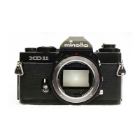
An XD-11 that's beyond economical
repair may then be worth purchasing; you
can use the body casting to make the
special tool. But, in most situations, you
won't have to adjust the two variable
resistors anyway. If the other adjustments
are correct, the LED readout should also
be correct. We'll describe the adjustment
sequence a little later. For now, just
remember to avoid disturbing the two
variable resistors on the side of the mirror
cage.
Figure 46 Electronic setting
Figure 48
 Loading...
