ARMATURE
modular, electronic focal-plane shutters. And, since some
cameras don't provide a clearance cutout over the eccentric, you
may find that the test circuit comes in handy. A little later, we'll
describe a couple of different ways you can build the test circuit.
MECHANICAL OPERATION OF THE SEIKO SHUTTER
Advance the shutter-cocking lever. Fig. 82, to cock the shutter.
Notice that the opening-blade set, Fig. 84, doesn't move during
the cocking cycle — it's already at the top of the aperture. But the
closing-blade set, visible from the back of the shutter, moves up
during the cocking cycle.
To release the shutter, push down the release lever, Fig. 84.
The opening blade should then move down, uncovering the aper
ture. However, the closing blade should remain latched to keep
the shutter open.
To free the closing blade, push the bulb lever out of engage
ment with the armature — from left to right in Fig. 84. The spring-
loaded armature then moves away from the electromagnet and
strikes the closing-blade latch. When the closing blade moves
down to end the exposure, it strikes a latch holding the opening
blade.
Figure 81 Shutter-terminal board Figure 83
through the electromagnet, the Seiko delivers a mechanical
speed that's very close to 1/1000 second. Consequently, you may
find that you’re trying to adjust the trigger switch when you're
really getting the mechanical speed. By first checking the opera
tion at a slower speed, you can at least be certain that you’ve
properly connected the test circuit.
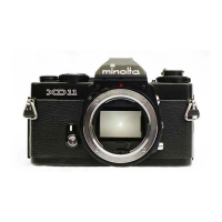
For the XD 11 alone, the test circuit may not be worth the
trouble. However, you can use the test circuit for any of the
ELECTROMAGNET
WIRES
TRIGGER-
SWITCH
CONNECTION I
TRIGGER-SWITCH
ECCENTRIC
RELEASE-LEVER
SPRING
LECTROMAGNET
SHUTTER-COCKING
LEVER
CLOSING-
BLADE
RA TC HET
Figure 82
Figure 84
 Loading...
