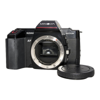
Figure 92
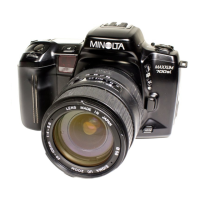
Figure 93
MAGNET
BRIDGE
X-CONTACT
CLOSING
LEVER
OPENING-BLADE
DRIVE
SPRING
timing cam as shown in Fig. 91.
You can now lift out the magnet
bridge, Fig. 92. Also lift out the opening-
blade drive spring, Fig, 93. The longer
end of the opening-blade drive spring
goes down and hooks against a tab on
the opening-blade driving lever. Leave the
closing-blade drive spring in place.
To remove the opening-blade latch,
first disconnect its spring from the tab on
the X-contact closing lever, Fig. 93. Then
lift the opening-blade latch up and off its
post. The spring stays on the opening-
blade latch.
At this point, you can more easily
observe the operation of the blade
assemblies. Be careful, though, that you
don't lift up the blade-driving levers. If
you do, the pins on the other sides of the
blade-driving levers will come out of the
slots in the blade sets. Then, if the in
dividual blades shift in position, you'll
have to realign the slots before you can
replace the blade-driving levers.
Fig. 94 and Fig. 95 show how the
blade-driving levers operate. As you cock
the shutter, the shutter-cocking lever
comes against a roller on the opening-
blade driving lever (this roller is the part
that may be sheared off if the shutter has
been forced). The shutter-cocking lever
now pushes up the opening-blade driving
lever. In turn, the opening-blade driving
lever pushes up the closing-blade driving
lever. With the shutter cocked, the
opening-blade latch, Fig. 93, engages the
opening-blade driving lever and the
closing-blade latch, Fig. 95, engages the
closing-blade driving lever.
Figure 94
Figure 95
I

 Loading...