NV8500 family Digital Routers • User’s Guide 15
1. Introduction
Signal Rates and Flow
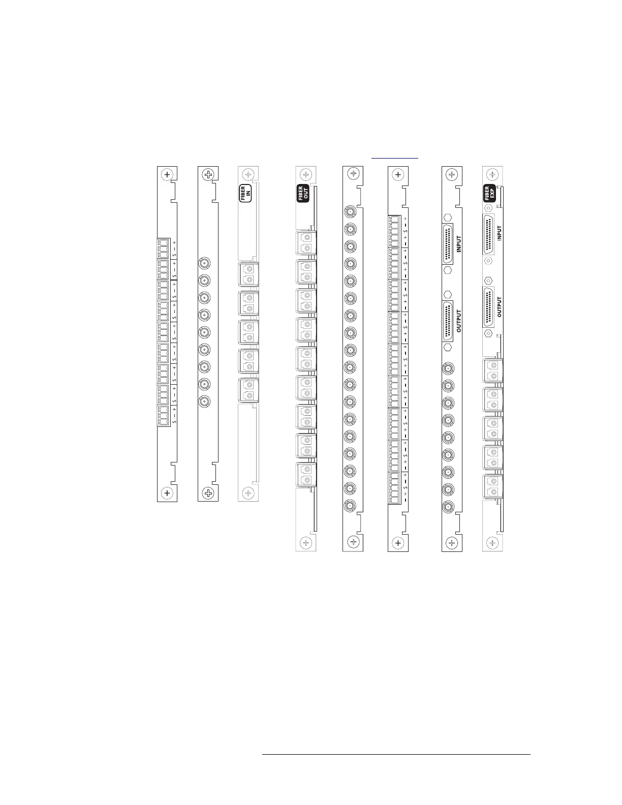
Figure 1-10 is an example of connectors on a backplane installed in either Input Slot 1 for inputs,
Output Slot 1 for outputs, or Output Slot 1 for expansion signals plus outputs. Each connector cor-
responds to a signal number with the lowest signal number—in this example ‘1’—at the top
ascending in order to the last connector.
For details on each backplane type and connectors, see Backplanes
on page 29.
Figure 1-10. Example of Signal Numbering for Backplanes in Slot 1
Card Slot and the Range of Signal Numbers
Active cards are inserted in slots through the front of the router and connect to corresponding back-
planes installed on the rear of the frame. When viewed from the front of the router, card slots are
numbered in ascending order from left-to-right, such that Slot 1 is the first slot on the left, Slot 2 is
the next card slot to the right of Slot 1, Slot 3 is the next card slot to the right of Slot 2,and so on.
The slot into which the card is installed determines the range of signal numbers assigned to the
backplane. For example, an input card is installed in Input Slot 1 manages inputs 1–9. The connec-
1
2
3
4
5
6
7
8
9
1
2
3
4
5
7
8
9
6
1
2
3
4
5
7
8
9
6
10
11
12
13
14
15
16
17
18
1
2
3
4
5
6
7
8
9
10
11
12
13
14
15
16
17
18
1
2
3
4
5
6
7
8
9
1
2
3
4
5
7
8
9
6
10
11
12
13
14
15
16
17
18
1
2
3
4
5
6
7
8
9
1
2
3
4
5
7
8
9
6
Not
used
Not
used
Input Backplanes
Output Backplanes
Expansion
Backplanes
with Output
Connectors