60 Rev 2.2 • 27 Mar 10
2. Installation
Making Signal Connections
How to Make Local I/O Connections
1 Locate the input connections at the rear of the router. Connectors are on backplanes containing
9 DIN 1.0/2.3, 9 LC or 9 WECO connectors each.
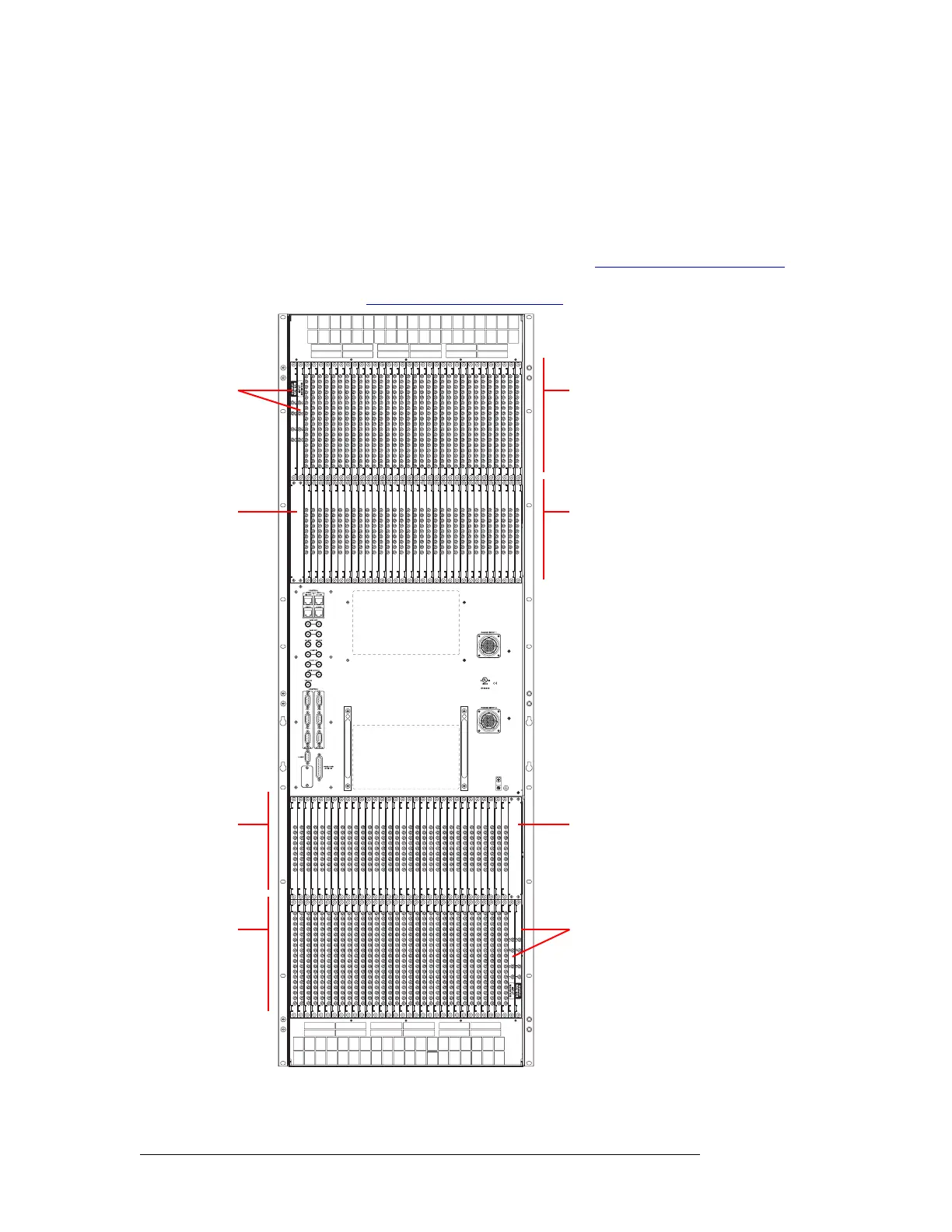
Figure 2-7, shows the backplane locations at the rear of an NV8576 router. For the NV8576-
Plus, the backplane location is identical, but the output backplanes have unique connectors for
connecting to a second NV8576-Plus router frame. (See Expansion Signal Connections
on page
64.) For an enumeration of the NV8576 and NV8576-Plus I/O connectors and corresponding
signal number, see NV8576 I/O Signal Numbering
on page 119.
Figure 2-7. NV8576 Frame with DIN 1.0/2.3 Backplanes (Rear View)
Monitor
Backplanes
(2)
Control card area
(no backplanes)
Output
Backplanes
(32)
Input
Backplanes
(32)
Unused
Monitor
Backplanes
(2)
Input
Backplanes
(32)
Output
Backplanes
(32)