NV8500 family Digital Routers • User’s Guide 85
2. Installation
Connecting to Power
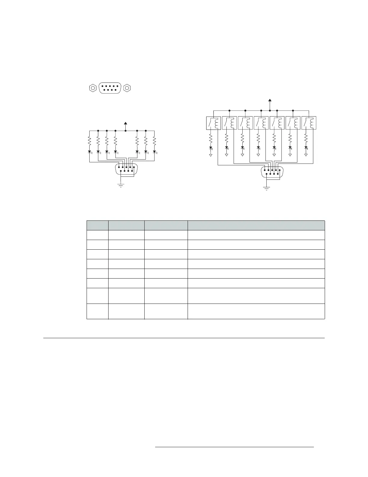
To create an indicator box, connect to the ‘ALARM’ connection using a DE9 female connector,
wiring as shown in Figure 2-30. Each pin monitors a specific function and activates a specific
alarm.
Figure 2-30. Alarm Connections and On/Off Switches
The following lists each DE9 pin and the associated alarm. The pin number listed corresponds to
the pin numbers in Figure 2-30 on page 85:
Connecting to Power
Routers in the NV8500 family use power supply modules to power the router frames. The NV8144
uses the PS8100 modules (850
Watts each), which are inserted directly in to the router frame. The
NV8280/NV8280-Plus and NV8576/NV8576-Plus routers use Miranda’s NV8000 power supply,
an external frame that holds up to four PS8100 power supply modules (850
Watts each). Each
NV8000 holds up to two primary power supply modules and two redundant power supply modules.
Typical Circuit 1
Customer-supplied relay
contacts NC, (but open during
alarm condition)
External Power,
30VDC max, 150 mA max
Normally ON, the LEDs turn off to indicate failure
1
COM
Normally OFF, the LEDs turn on to indicate failure
30VDC max, 150 mA max
External Power
1
12345
6789
1
2
3
4
5
Alarm COM
Alarm 1
Alarm 2
Alarm 3
Alarm 4
8
7
8
9
Alarm 5
Alarm 6
Alarm 7
Alarm COM
Typical Circuit 2
COM
PIN Signal Description Possible Conditions Causing the Alarm
1, 9 Alarm_COM Common Common connection for all alarm pins.
2 Alarm_1 Major Alarm Indicates missing reference inputs, or missing power supplies.
3 Alarm_2 Minor Alarm Alarm_3, or Alarm_4, or Alarm_5, or Alarm_6
4 Alarm_3 Power Supply Missing power supply module.
5 Alarm_4 Video Ref Missing Video Ref 1 or Video Ref 2.
6 Alarm_5 AES Ref Not used in NV8500 family.
7 Alarm_6 Fans or
Temperature
Indicates a fan failure or module over temperature.
8 Alarm_7 Control Module
Health
Any control module not “healthy.”