56
7521
7521
N/B MAINTENANCE
N/B MAINTENANCE
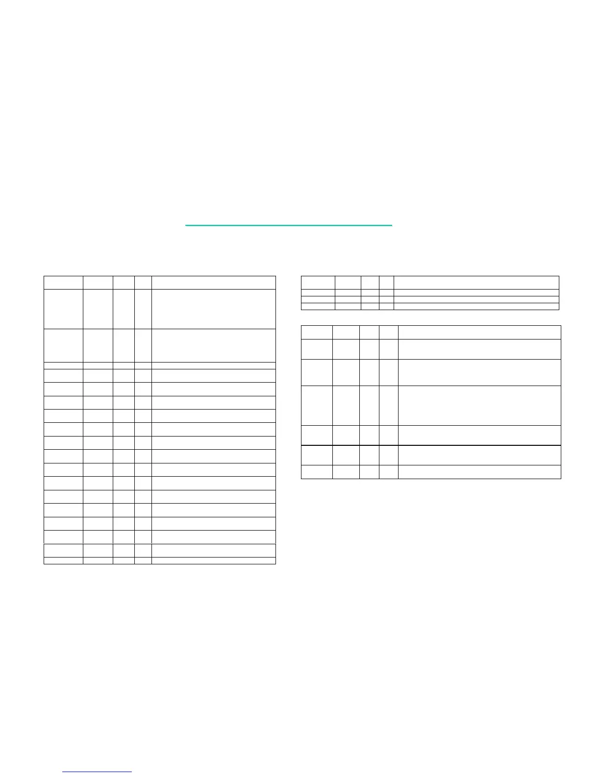
VGA Interface
Name Tolerance Power
Plane
Type
Attr
Description
VMA11
VGCLK
3.3V MAIN O
O
Display Memory Address bit 11 : When 128bits
DRAM interface enable, it represents the Memory
Address bit 11
Digital Video Clock Output: When Video Bridge
connected, it represents the Digital Video Clock
Output
VMA10
VBHCLK
3.3V MAIN O
O
Display Memory Address bit 10: When 128bits
DRAM interface enable, it represents the Memory
Address bit 10
Control Clock Output: When Video Bridge
connected, it represents the Control Clock Output
VMD[63:60] 3.3V MAIN I/O Display Memory Data Bus bits [63:60]
VMD[59:52]
VBRGB[7:0]
3.3V MAIN I/O
O
Display Memory Data Bus bits [59:52]
Digital Video Data bits [7:0]
VMD[51:49]
VBRGB[18:16]
3.3V MAIN I/O
O
Display Memory Data Bus bits [51:49]
Digital Video Data bits [18:16]
VMD[48:44]
VBRGB[19:23]
3.3V MAIN I/O
O
Display Memory Data Bus bits [48:44]
Digital Video Data bits [19:23]
VMD[43:42]
VBRGB[10:11]
3.3V MAIN I/O
O
Display Memory Data Bus bits [43:42]
Digital Video Data bits [10:11]
VMD[41:40]
VBRGB[9:8]]
3.3V MAIN I/O
O
Display Memory Data Bus bits [41:40]
Digital Video Data bits [9:8]
VMD[39:38]
VBRGB[13:12]
3.3V MAIN I/O
O
Display Memory Data Bus bits [39:38]
Digital Video Data bits [13:12]
VMD[37:36]
VBRGB[14:15]
3.3V MAIN I/O
O
Display Memory Data Bus bits [37:36]
Digital Video Data bits [14:15]
VMD35
VBBLANKN
3.3V MAIN I/O
O
Display Memory Data Bus bit 35
Digital Video Display Enable
VMD[34:33]
TVCTL[0:1]
3.3V MAIN I/O
O
Display Memory Data Bus bits [34:33]
Video Bridge Data Control bits [0:1]
VMD32
VBCAD
3.3V MAIN I/O
I/O
Display Memory Data Bus bit 32
Video Bridge Programming Control
VMD31
VBHSYNC
3.3V MAIN I/O
I/O
Display Memory Data Bus bit 31
Digital Video Horizontal Sync
VMD30
VBVSYNC
3.3V MAIN I/O
I/O
Display Memory Data Bus bit 30
Digital Video Vertical Sync
VMD29
DDC2CLK
3.3V MAIN I/O
I/O
Display Memory Data Bus bit 29
Second Display data channel clock line
VMD28
DDC2DATA
3.3V MAIN I/O
I/O
Display Memory Data Bus bit 28
Second Display data channel data line
VMD[27:0] 3.3V MAIN I/O Display Memory Data Bus bits [27:0]
Name Tolerance Power
Plane
Ty p e
Attr
Description
VDQM[7:0]
3.3V MAIN O Display Memory SDRAM Input /Output Mask
OSCI
3.3V/5V MAIN I External 14.318MHz Clock Input
ENTEST
3.3V/5V MAIN I Test Mode Enable
Power management Interface
Name Tolerance Power
Plane
Ty pe
Attr
Description
ACPILED
<=5V AUX OD
ACPILED :
ACPILED can be used to control the
blinking of an LED at the frequency of 1 Hz to indicate the system is at power
saving mode.
EXTSMI#
3.3V/5V MAIN I
External SMI#:
EXTSMI# can be used to generate
wakeup event, sleep event, or SCI/SMI#/GPEIRQ event to the ACPI-
compatible power management
unit.
PME#
3.3V/5V AUX I/O
PME# :
When the system is in power-down mode, an active low event on
PME# will cause the PSON# to go low and hence turn on the power supply.
When
the system is in suspend mode, an active PME# event will cause the system
wakeup and generate an
SCI/SMI#/GPEIRQ.
PSON#
<=5V AUX OD
ATX Power ON/OFF control:
PSON# is used to control the on/off state of
the ATX power supply. When the ATX power supply is in the OFF state, an
activated power-on event will force the power supply to ON state.
PWRBTN#
3.3V/5V AUX I
Power Button:
This signal is from the power button
switch and will be monitored by the ACPI- mpatible power management unit
to switch the system between working and sleeping states.
RING
3.3V/5V AUX I
Ring Indication :
An active RING pulse and lasting for more than 4ms will
cause a wakeup event for system to wake from S1~S5.
4. Pin Descriptions Of Major Components
4.2 SiS630 Slot 1/Socket 370 2D/3D Ultra-AGP™ Single Chipset
 Loading...