and techniques that allow them to withstand high temperatures without damage. Additionally, care
must be taken when performing a “Probe-Zero” or “Calibration to Known Thickness” with a high
temperature transducer.
Selection of the proper transducer is often a matter of tradeoffs between various characteristics. It
may be necessary to experiment with a variety of transducers in order to find one that works well for a
given job.
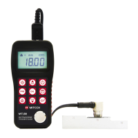
The transducer is the “business end” of the instrument. It transmits and receives ultrasonic sound
waves that the instrument uses to calculate the thickness of the material being measured. The
transducer connects to the instrument via the attached cable, and two coaxial connectors. When using
transducers, the orientation of the dual coaxial connectors is not critical: either plug may be fitted to
either socket in the instrument.
The transducer must be used correctly in order for the instrument to produce accurate, reliable
measurements. Below is a short description of the transducer, followed by instructions for its use.
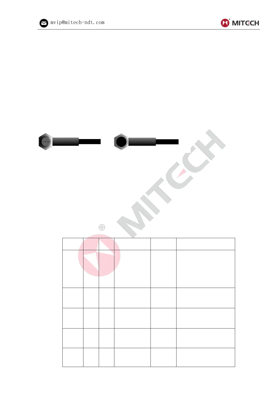
Left figure is a bottom view of a typical transducer. The two semicircles of the wearface are visible,
as is the barrier separating them. One of the semicircles is responsible for conducting ultrasonic
sound into the material being measured, and the other semicircle is responsible for conducting the
echoed sound back into the transducer. When the transducer is placed against the material being
measured, it is the area directly beneath the center of the wearface that is being measured.
Right figure is a top view of a typical transducer. Press against the top with the thumb or index
finger to hold the transducer in place. Moderate pressure is sufficient, as it is only necessary to keep
the transducer stationary, and the wearface seated flat against the surface of the material being
measured.
Table 3-1 Transducer Selection
3.0mm~
300.0mm(In
Steel)
40mm (in Gray
Cast Iron
HT200)
for thick, highly
attenuating, or highly
scattering materials
For thin pipe wall or small
curvature pipe wall
measurement
For high temperature
(lower than 300℃)
measurement.