5
RSM Switch Modules
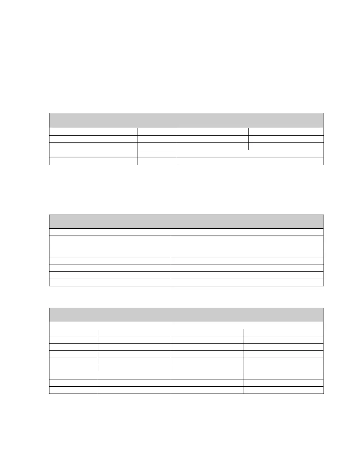
Weight.................................................................................................................. 1 pound nominal
Chassis Dimensions.................................................................5.6” wide x 1.61” high x 1.90” deep
........................................................................excluding connectors(see outline drawing 157773)
RF connectors............................................................................................................. SMA female
IF Connectors...............................................................................................................BNC female
Switch Module Bus Connectors ..................................................................Serial ATA Receptacle
1.2.2 CONNECTOR WIRING INFORMATION
Converter Control and Status Connectors* (J1 through J13)
9-pin D-subminiature
Function Pins Normal Fault
Converter Fault Inputs 1,2 Open Closed
Converter Fault Inputs 2,3 Closed Open
Converter Control Bus Data- 5 N/A
Converter Control Bus Data+ 9 N/A
• The Control Unit must sense both Normally Open and Normally Closed contacts.
This provides the means for the Control unit to automatically recognize that a
converter has been added to the chain or removed from the chain.
Table 1-1. NSUN Switch Connections
Switch Module Bus Connectors (J14 and J15 NSUN Only)
Connector type Serial ATA
Pin Designation
1 Ground
2 Data +
3 +24V ‘A’
4 +24V ‘A’ Return
5 Data-
6 +24V ‘B’
7 +24V ‘B’ Return
Table 1-2. NSU Remote Interface Connections
Control Unit Remote Interface and Status Connector (J16)
9-Pin D-Subminiature
RS485 and RS422 RS232
Pin Designation Pin Designation
1 Ground 2 RCV Data
3 Data Out - 3 Tx Data
5 Data In - 5 Ground
7 Data Out + 7 RTS
9 Data In + 8 CTS
2 Normally Open 1 Normally Open
4 Common 4 Common
6 Normally Closed 6 Normally Closed