Page 17
Connection to switch provided.
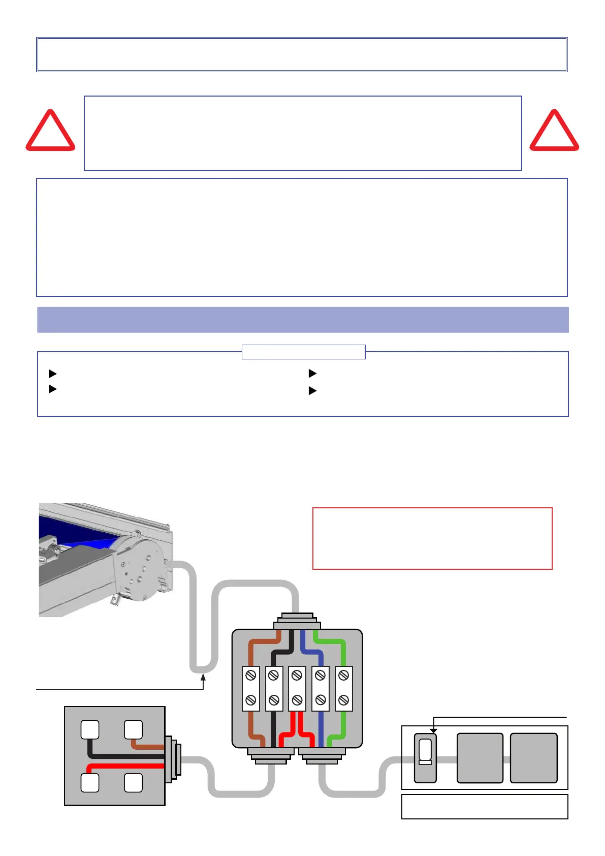
Connections Box
x2x1
L
Cable B Cable A
Necessary material
Material not provided
Watertight junction box (IP54)
Bypass strip
Cable (A) 3G 1.5mm² (blue, red, green / yellow)
Cable (B) 3G 1.5mm² (black, red, brown)
SWITCH
ATTENTION
For your safety, before any installation and connection operation, make sure that the power is off
(line disconnected).
- Do not spray water on the automatism unit.
!
CAUTION
- You have purchased an automatism, the connection operations must be carried out by competent persons for a
correct installation and binding guarantee.
- Cut off the power before any connaction or manipulation of the automatism.
- Do not allow children to play with the control devices (remote control).
- Check the installation frequently for any poor balance or any signs of wear.
- Do not use the pergola if it needs to be repaired or adjusted.
!
For all motors, the installation must comply with the NFC15-100 standard
MOTORIZATION
Independent line from any installation
External cables protected by a sheath
Electric board
Differential
30mA
10A switch. Not provided.
Elbow to perform. (Water lift)
L1
N
PE
L1
L2
L2
N
PE
A - Connect the cables inside the watertight junction box.
B - Close the junction box.
C - Restore power and run a test.
IMPORTANT
Make a rst connection in order to continue installing
the product. The motor cable output of the product will
be carried out later. Refer to page 16
paragraph motor cable outlet.
 Loading...