Page 18
L1 L1
N N
L2 L2
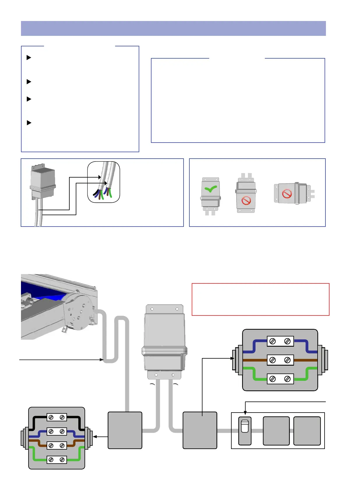
REMOTE CONTROL MOTORIZATION
CAUTION
Before any installation, determine in relation to the location
of your store:
- The location of your automation, this location must allow
the automation to pick up signals in order to ensure maxi-
mum sensitivity of the control.
- The xing of the electronic card housing must be vertical
and protected from bad weather.
Never open the electronic box. (Cancellation of warranty)
Fixing the box: 4 Ø2.5mm screws.
The housing must be xed vertically and protected from the elements.
Motor power cable (C1)
Power cord (C2)
Technical characteristics of the radio
remote control unit.
Voltage: 230 volts
Frequency: 50Hz
Power: 1.5va
Protection index: IP65
MOTOR: 230v - 50H 500w maxi
(C1)
(C2)
Electric
board
Differential
30mA
10A switch. Not provided.
(C1)
(C2)
IP54 junc-
tion box.
Not provi-
ded.
IP54 junc-
tion box.
Not provi-
ded.
Elbow to perform. (Water lift)
A - Connect the cables inside the watertight junction box.
B - Close the junction box.
C - Restore power and program the motor.
PE PE
L L
N N
PE PE
IMPORTANT
Make a rst connection in order to continue installing
the product. The motor cable output of the product will
be carried out later. Refer to page 16
paragraph motor cable outlet.
2 watertight junction boxes
(IP54)
Bypass strip
Cable (A) 3G 1.5mm²
(blue, red, green / yellow)
Cable (B) 3G 1.5mm²
(black, red, brown)
Necessary material
Material not provided
 Loading...