54
TCH123
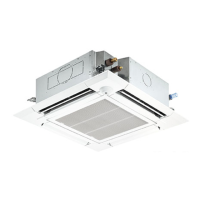
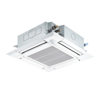
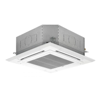
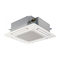
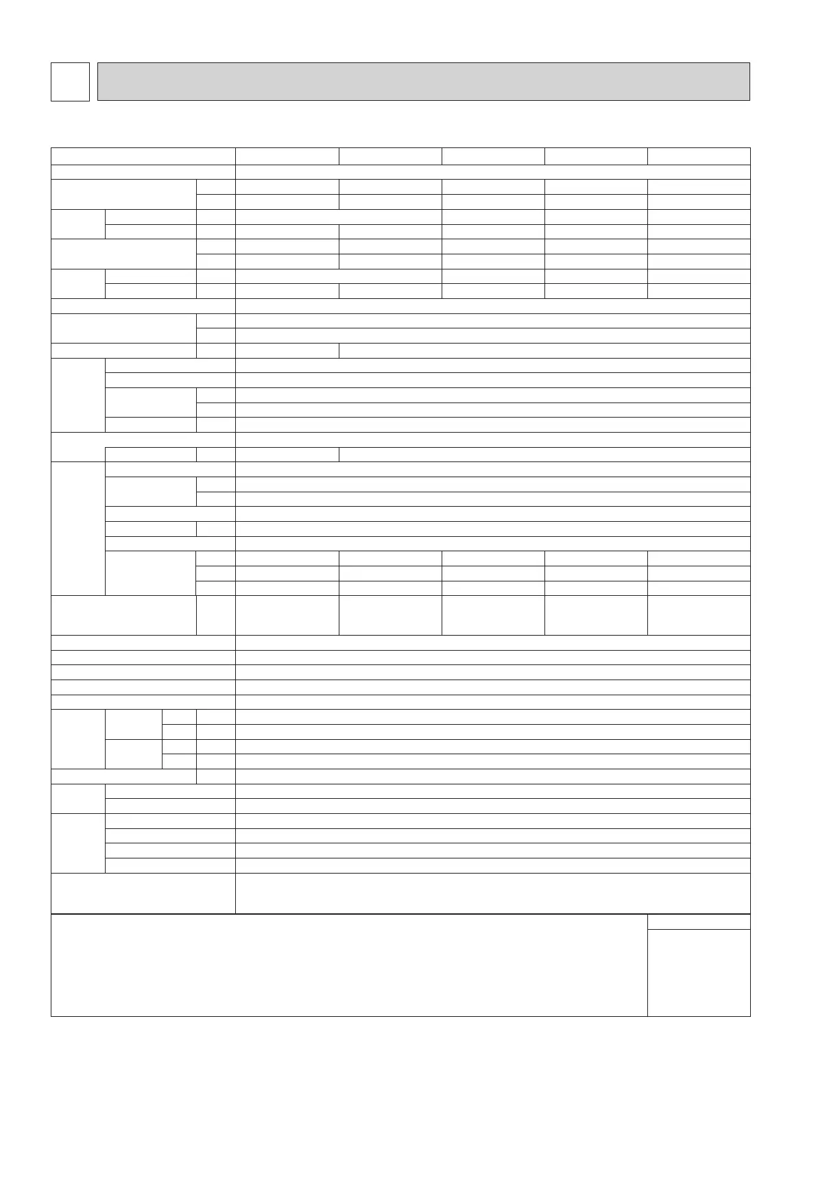
3-1. SPECIFICATIONS
3
SPECIFICATIONS
Model
PLFY-WL04NFMU-E.TH PLFY-WL06NFMU-E.TH PLFY-WL08NFMU-E.TH PLFY-WL12NFMU-E.TH PLFY-WL15NFMU-E.TH
Power source 1-phase 208/230 V 60Hz
Cooling capacity
*1
(Nominal)
*1
BTU/h 4,000 6,000 8,000 12,000 15,000
kW 1.2 1.8 2.3 3.5 4.4
Power input kW 0.2 0.03 0.04 0.05
Current input
A 0.23 0.26 0.29 0.38 0.46
Heating capacity
*2
(Nominal)
*2
BTU/h 4,500 6,700 9,000 13,500 17,000
kW 1.3 2.0 2.6 4.0 5.0
Power input kW 0.02 0.03 0.04 0.05
Current input
A 0.17 0.20 0.23 0.32 0.40
External nish Galvanized steel plate
External dimension
H × W × D
inch 8-3/16 × 22-7/16 × 22-7/16
mm 208 × 570 × 570
Net weight lbs (kg) 29 (13) 31 (14)
Decoration
panel
model SLP-18FAU
External nish MUNSELL (1.0Y 9.2/0.2)
Dimension
H × W × D
inch 13/32 × 24-19/32 × 24-19/32
mm 10 × 625 × 625
Net weight lbs (kg) 7 (3)
Heat exchanger Cross n (Aluminum n and copper tube)
Water volume L 0.5 0.9
FAN Type × Quantity Turbo fan × 1
External static
press.
in.WG 0
Pa 0
Motor type DC motor
Motor output kW 0.05
Driving mechanism
Direct-driven
Airow rate
(Low-Mid-High)
cfm
212 - 230 - 247 230 - 247 - 282 230 - 265 - 318
230 - 318 - 424
230 - 406 - 459
K/min
6.0 - 6.5 - 7.0
6.5 - 7.0 - 8.0
6.5 - 7.5 - 9.0 6.5 - 9.0 - 12.0 6.5 - 11.5 - 13.0
L/s
100 - 108 - 117
108 - 117 - 133
108 - 125 - 150 108 - 150 - 200 108 - 192 - 217
Sound pressure level
(Low-Mid-High)
(measured in anechoic room)
dB <A>
25 - 26 - 27 27 - 29 - 31 27 - 30 - 34 27 - 33 - 41 27 - 40 - 43
Insulation material PS
Air lter PP honeycomb fabric (long life type)
Protection device Fuse
Refrigerant control device —
Connectable HBC controller CMB-WP-NU-AA, CMB-WP-NU-AB
Water
piping
diameter
*3,*4
Connection
size
Inlet
mm O.D.
22
Outlet
mm O.D.
22
Field pipe
size
Inlet mm I.D.
20
Outlet mm I.D.
20
Field drain pipe size
inch (mm)
O.D. 1-1/4 (32)
standard
attachment
Document
Installation Manual, Instruction Book
Accessory
Insulation template, Washer, Drain socket, Tie band
Optional
parts
Decoration panel
SLP-18FAU
3D i-see Sensor panel
SLP-18FAEU
3D i-see Sensor corner panel
PAC-SF1ME-E
Wireless signal receiver PAR-SF9FA-E
Remark * Details on foundation work, duct work, insulation work, electrical wiring, power source switch, and other
items shall be referred to the Installation Manual.
* Due to continuing improvement, above specications may be subject to change without notice.
Notes:
1. Norminal cooling conditions
Indoor: 80°FD.B./67°FW.B. (26.7°D.B./19.4°CW.B.), Outdoor: 95°FD.B. (35°CD.B.)
Pipe length: 25 ft. (7.6 m), Level difference: 0 ft. (0 m)
2. Norminal heating conditions
Indoor: 70°FD.B. (21.1°C.B.), Outdoor: 47°FD.B./43°FW.B. (8.3°CD.B./6.1°CW.B.)
Pipe length: 25 ft. (7.6 m), Level difference: 0 ft. (0 m)
3. Be sure to install a valve on the water inlet/outlet.
4. Install a strainer (40 mesh or more) on the pipe next to the valve to remove the foreign matters.
Unit converter
Btu/h = kW × 3,412
cfm = m³/min × 35.31
lb = kg/0.4536
*Above specication
data is subject to
rounding variation.
 Loading...