Do you have a question about the Mitsubishi Electric CITY MULTI PUMY-P200YKM3 and is the answer not in the manual?
| Model | PUMY-P200YKM3 |
|---|---|
| Series | CITY MULTI |
| Category | Air Conditioner |
| Brand | Mitsubishi Electric |
| Cooling Capacity | 20.0 kW |
| Heating Capacity | 22.4 kW |
| Refrigerant | R410A |
| Sound Pressure Level | 58 dB(A) |
| Type | Heat Pump |
| Power Supply | 3 Phase, 400V, 50Hz |
| Operating Temperature Range (Cooling) | -5°C to 46°C |
| Operating Temperature Range (Heating) | -20°C to 15°C |
Details safety precautions for R410A refrigerant, including preparation and during repair.
Guidelines for maintaining salt-proof models, focusing on installation and cleaning to prevent rust.
Specifics on R410A refrigerant piping, including pipe thickness and flare dimensions for safe installation.
Details various system configurations, connectable indoor units, and remote controller compatibility.
Explains system configurations utilizing branch boxes and their connectable indoor unit lineups.
Describes system configurations for mixed systems involving branch boxes and various indoor units.
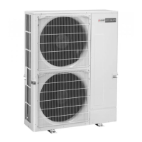
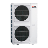
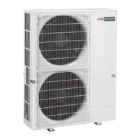
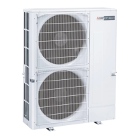
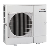
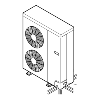
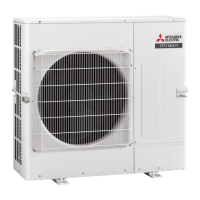
Provides detailed specifications for the P200 outdoor unit, including capacity and model identification.
Guidance on selecting appropriate indoor and outdoor units based on cooling and heating calculations.
Explains how to correct cooling/heating capacity based on indoor and outdoor temperatures using correction factors.
Details how to adjust capacity based on refrigerant piping length and bends for cooling and heating.
Provides a method to correct heating capacity for frost and defrosting conditions using a correction factor table.
Procedures and safety checks to perform before conducting a test run of the unit.
Specific instructions for performing a test run using the M-NET remote controller.
Lists error codes and their corresponding countermeasures during test runs.
Instructions for removing the service panel and top panel of the outdoor unit for access.
Step-by-step guide to safely remove the fan motor components from the outdoor unit.
Procedure for accessing and removing the electrical parts box containing circuit boards and wiring.
Detailed steps for removing the suction pipe thermistor (TH6) and its associated wiring.
Instructions for removing the ambient thermistor (TH7), noting its combined replacement with TH6.
Procedure for removing multiple thermistors including outdoor liquid pipe, compressor, and HIC pipe.
Steps to remove the 4-way valve coil, including disconnecting connectors and removing screws.
Detailed procedure for removing the 4-way valve assembly, including associated components and refrigerant recovery.
Instructions for removing the bypass valve coil and the bypass valve assembly.
Steps to remove the high pressure switch (63H), including refrigerant recovery and welded part removal.
Procedure for removing the low pressure sensor (63LS) and high pressure sensor (63HS).
Steps for removing the linear expansion valve coils (LEV-A, LEV-B), including refrigerant recovery.
Instructions for removing the reactor (DCL) from the electrical parts box.
Detailed procedure for removing the compressor, including associated parts and refrigerant recovery.
Steps for removing the accumulator, including its inlet, outlet, and leg fixing screws.
Illustrates typical refrigerant piping and transmission cable wiring configurations for the system.
Schematic diagram showing the refrigerant flow and components within the system.
Reference to installation manual for details on refrigerant piping systems, including length and height differences.
Details precautions against refrigerant leakage, including maximum concentration limits and confirmation procedures.
Explains the functions and interface of the PAR-41MAA remote controller, covering display and button operations.
Guide to checking error information, accessing the service menu, and performing basic maintenance.
Details procedures for self-diagnosis of units and checking the remote controller's functionality.