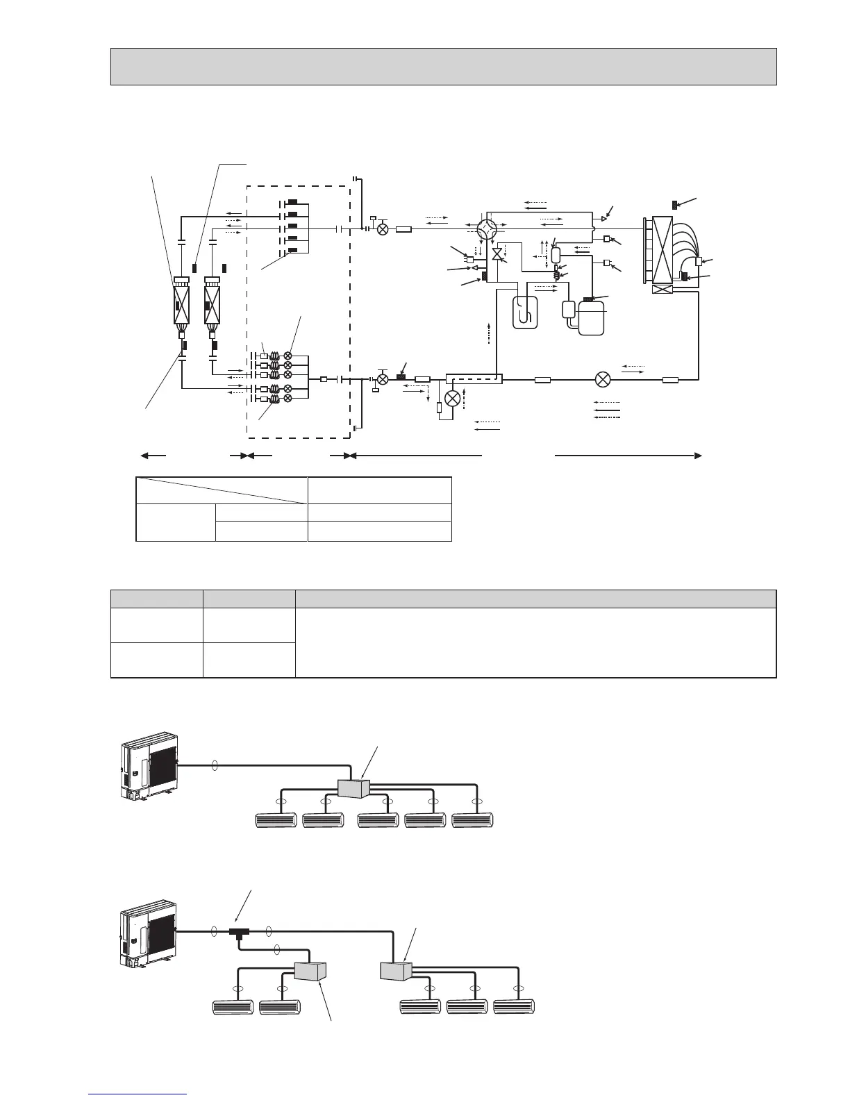
■Incaseofusing1-branchbox
Flareconnectionemployed(Nobrazing)
A
B
Liquid(mm) {9.52
Gas (mm) {15.88
Thepipeconnectionsizediffersaccordingtothetypeandcapacityofindoorunits.
Matchthepipingconnectionsizeofbranchboxwithindoorunit.
Ifthepipingconnectionsizeofbranchboxdoesnotmatchthepipingconnectionsize
ofindoorunit,useoptionaldifferent-diameter(deformed)jointstothebranchboxside.
(Connectdeformedjointdirectlytothebranchboxside.)
■Installationprocedure(2branchpipe(joint))
Refer to the installation manuals of
MSDD-50AR-E.
Capillary tube
E
D
C
B
A
Strainer
#100
Condenser / evaporator
temperature thermistor
(TH5 or RT12)
Pipe temperature
thermistor / liquid
(TH2 or RT13)
Strainer
#100
Indoor units Branch box Outdoor unit
Thermistor (TH-A–E)
(Gas pipe temperature)
LEV A–E
(Linear expansion valve)
Room temperature
thermistor (TH1 or RT11)
E
D
C
B
A
([4.0 o [3.0 o L130) o 5
PAC-MK31/33BC(B)
Branch box
Capillary tube behind LEV
(in cooling mode)
([4.0 o [3.0 o L130) o 3
Unit: mm
PAC-MK51/53BC(B)
Solenoid
valve
(SV1)
High pressure
sensor (63HS)
High pressure
switch (63H)
Low pressure
sensor(63LS)
Oil separator
Service port
Distributor
Compressor
Thermistor (TH4)
<
Compressor
>
Thermistor (TH7)
<Ambient>
<Outdoor liquid pipe>
Thermistor (TH3)
Ball valve
Strainer
4-way valve
Check valve
<Low pressure>
Thermistor (TH6)
<Suction pipe>
Check valve
<High pressure>
Strainer
Strainer
LEV-B
HIC
LEV-A
Strainer
Strainer
Thermistor (TH2)
<HIC pipe>
Stop valve
Service port
Capillary
tube
Accumulator
Strainer
Refrigerant flow in cooling
Refrigerant flow in heating
Refrigerant flow in cooling (Main)
Refrigerant flow in heating (Main)
Refrigerant flow in cooling (Sub)
 Loading...