8 TROUBLESHOOTING
Notes:
1.Ifcheckcodeappearsonremotecontrollerorremotecontrollermalfunctions,referto“8-1-2.CountermeasuresforErrorDuringRun”.
2.
Duringtestrunoperation,2-hourofftimeractivatesautomaticallyandremainingtimeisdisplayedonremotecontrollerandtestrunwillstop2hours
later.
3.Duringtestrun,theindoorliquidpipetemperatureisdisplayedonremotecontrollerinsteadofroomtemperature.
4.
Dependingonamodel,“Thisfunctionisnotavailable”appearswhenairdirectionbuttonispressed.However,thisisnotmalfunction
.
8-1. CHECK POINTS FOR TEST RUN
8-1-1. Procedures before test run
(1)Beforetestrun,makesurethatthefollowingworkiscompleted.
•Installationrelated:
Makesurethatthepanelofcassettetypeandelectricalwiringaredone.
Otherwiseelectricalfunctionslikeautovanewillnotoperatenormally.
•Pipingrelated:
Performleakagetestofrefrigerantanddrainpiping.
Makesurethatalljointsareperfectlyinsulated.
Checkstopvalvesonbothliquidandgassideforfullopen.
•Electricalwiringrelated:
Checkgroundwire,transmissioncable,remotecontrollercable,andpowersupplycableforsecureconnection.
Makesurethatallswitchsettingsofaddressoradjustmentsforspecialspecificationsystemsarecorrectlysettled.
(2) Safety check :
Withtheinsulationtesterof500V,inspecttheinsulationresistance.
Donottouchthetransmissioncableandremotecontrollercablewiththetester.
The resistance should be over 1.0 M".Donotproceedinspectioniftheresistanceisunder1.0M".
Inspectbetweentheoutdoorunitpowersupplyterminalblockandgroundfirst,metallicpartslikerefrigerantpipesorthe
electricalboxnext,theninspectallelectricalwiringofoutdoorunit,indoorunit,andalllinkedequipment.
(3)Beforeoperation:
a)Turnthepowersupplyswitchoftheoutdoorunittoonforcompressorprotection.Foratestrun,waitatleast12hours
fromthispoint.
b)Registercontrolsystemsintoremotecontroller(s).NevertouchtheON/OFFswitchoftheremotecontroller(s).Referto“7-2.
SpecialFunctionOperationandSettingsforM-NETRemoteController”asforsettings.InMAremotecontroller(s),this
registration is unnecessary.
(4)Morethan12hourslaterfrompowersupplytotheoutdoorunit,turnallpowerswitchtoonforthetestrun.Performtestrun
accordingtothe“Operationprocedure”tableofthebottomofthispage.Whiletestrunning,maketestrunreports.
8-1-1-1. Test run for M-NET Remote controller
(M-NET remote controller cannot be connected with a refrigerant system which includes branch box.
)
Whenyoudelivertheunitafterthetestrun,instructtheenduserforproperusageofthesystemusingowners’manual
and the
t
estrunreportyoumadetocertificatenormaloperation.Ifabnormalitiesaredetectedduringtestrun,referto“8-1-2.
CountermeasuresforErrorDuringTestRun”.AsforDIPswitchsettingofoutdoorunit,referto“8-5.INTERNALSWITCH
FUNCTIONTABLE”.
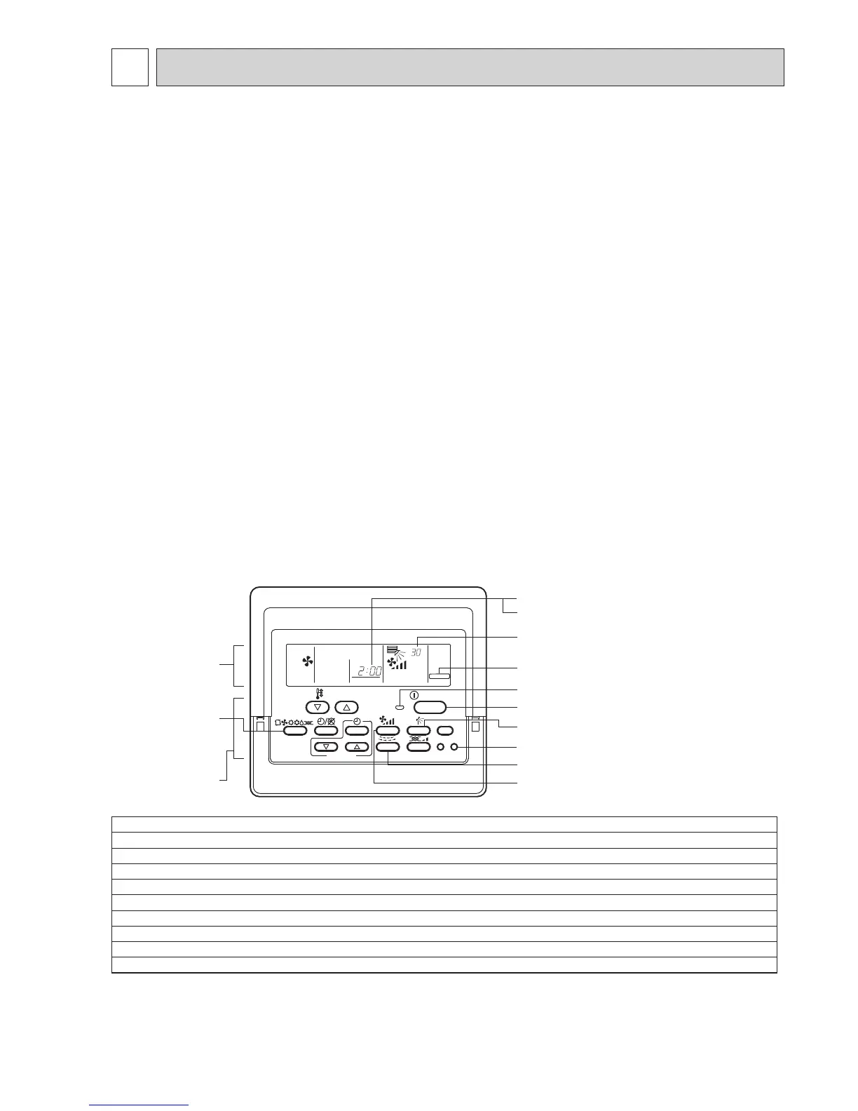
ON/OFF
TEST RUN
°C
1Hr.
FILTER
CHECK TEST
TEMP.
TIMER SET
Check code indicator (see Note 1)
Test run remaining time indicator (see Note 3)
Display panel
(M-NET Remote controller)
ON/OFF button 9
ON/OFF LED (Lights up in operation)
LOUVER button 6
TEST RUN button 2
AIR DIRECTION button 6
FAN SPEED button 5
TEST RUN indicator
Indoor unit liquid pipe temperature indicator
(see Note 4)
(Cooling/Heating)
OPERATION
SWITCH button
3,4
Control panel
Operationprocedure
1
Turnonthemainpowersupplyofallunitsatleast12hoursbeforetestrun.”HO”appearsondisplaypanelfor3minutes.
2
12hourslater,pressTESTRUNbuttontwicetoperformtestrun.“TESTRUN“appearsondisplaypanel.
3
PressOPERATIONSWITCHbuttontomakesurethatairblowsout.
4
SelectCooling(orHeating)byOPERATIONSWITCHbuttontomakesurethatcool(orwarm)airblowsout.
5
PressFanspeedbuttontomakesurethatfanspeedischangedbythebutton.
6
PressAIRDIRECTIONbuttonorLOUVERbuttontomakesurethatairdirectionisadjustable(horizontal,downward,upward,andeachangle).
7
Checkoutdoorfansfornormaloperation.
8
Checkinterlockeddevices(likeventilator)fornormaloperation,ifany.Thisistheendoftestrunoperation.
9
PressON/OFFbuttontostopandcanceltestrun.
 Loading...