EasyManua.ls Logo

Mitsubishi Electric City Multi Series PCFY-P15NKMU-E User Manual

Mitsubishi Electric City Multi Series PCFY-P15NKMU-E
36 pages
To Next Page IconTo Next Page
Page #1 background imageLoading...
Page #1 background image
TECHNICAL & SERVICE MANUAL
CONTENTS
1. TECHNICAL CHANGES
.........................
2
2. PART NAMES AND FUNCTIONS
..........
2
3. SPECIFICATION
.....................................
4
4. OUTLINES AND DIMENSIONS
..............
8
5. WIRING DIAGRAM
...............................
11
6. REFRIGERANT SYSTEM DIAGRAM
........
13
7. MICROPROCESSOR CONTROL
...............
14
8. TROUBLESHOOTING
..........................
21
9. DISASSEMBLY PROCEDURE
.............
30
Indoor unit
[Model names] [Service Ref.]
No. OCH500
REVISED EDITION-A
INDOOR UNIT
R22R410A
Note:
This manual describes only
service data of the indoor
units.
RoHS compliant products
have <G> mark on the spec
name plate.
April 2012
PARTS CATALOG (OCB500)
Model name
indication
SPLIT-TYPE, HEAT PUMP AIR CONDITIONERS
PCFY-P15NKMU-E
PCFY-P24NKMU-E
PCFY-P30NKMU-E
PCFY-P36NKMU-E
PCFY-P15NKMU-E.TH
PCFY-P15NKMU-ER1.TH
PCFY-P24NKMU-E.TH
PCFY-P24NKMU-ER1.TH
PCFY-P30NKMU-E.TH
PCFY-P30NKMU-ER1.TH
PCFY-P36NKMU-E.TH
PCFY-P36NKMU-ER1.TH
Revision:
PCFY-P15/24/30/36NKMU-
ER1 have been added in
REVISED EDITION-A.
• Some descriptions have
been modified.
• Please void OCH500.
Question and Answer IconNeed help?

Do you have a question about the Mitsubishi Electric City Multi Series PCFY-P15NKMU-E and is the answer not in the manual?

Mitsubishi Electric City Multi Series PCFY-P15NKMU-E Specifications

General IconGeneral
BrandMitsubishi Electric
ModelCity Multi Series PCFY-P15NKMU-E
CategoryAir Conditioner
LanguageEnglish

Summary

Technical Changes

Model Number Revisions

Lists model number updates in the latest edition.

Software Version Update

Notes a change in the indoor controller board's S/W version.

Part Names and Functions

Indoor Unit Component Identification

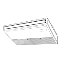
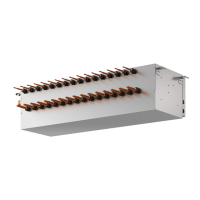
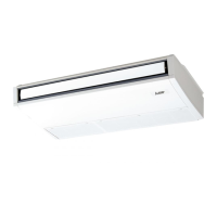
Identifies key components like louvers, air outlets, and filters.

Specifications

General Unit Specifications

Covers cooling/heating capacity, dimensions, weight, and materials.

Electrical and Component Specifications

Details electrical parts, motors, and pipe sizes.

Sound Level and Acoustic Data

Provides sound pressure levels and NC curves.

Airflow and Static Pressure Characteristics

Presents data on fresh air intake and static pressure.

Outlines and Dimensions

PCFY-P15NKMU-E Model Dimensions

Shows dimensions and connection points for the P15 model.

PCFY-P24NKMU-E Model Dimensions

Details dimensions and connection points for the P24 model.

PCFY-P30/P36NKMU-E Model Dimensions

Provides dimensions and connection points for P30/P36 models.

Wiring Diagram

Indoor Unit Electrical Connections

Illustrates wiring and component layout for indoor units.

Refrigerant System Diagram

Refrigerant Flow and Pipe Specifications

Diagram shows refrigerant flow and pipe diameters for different models.

Microprocessor Control

Cool Operation Control Details

Explains thermostat and anti-freezing logic in cool mode.

Dry Operation Control Details

Details control logic for thermostat, fan, and vanes in dry mode.

Fan Operation Control Details

Describes fan, drain pump, and vane control in fan-only mode.

Heat Operation Control Details

Covers thermostat, fan, and hot adjust modes during heating.

Auto Operation Control Logic

Explains mode transitions and operations in auto mode.

Troubleshooting

Component Resistance and Voltage Checks

Procedures for checking thermistors, motors, switches, and voltage.

Linear Expansion Valve Troubleshooting

Diagnosing LEV operation, coils, and valve closure issues.

Fan Motor and Circuit Board Diagnosis

Steps for troubleshooting DC fan motor and indoor controller board faults.

DIP Switch and Remote Controller Settings

Explains DIP switch functions and wireless remote pairing.

Indoor Controller Board Test Points

Diagram of test points on the indoor controller board for diagnostics.

Address Board Configuration

Details settings for address, ceiling height, and branch number.

Disassembly Procedure

Removing Air Intake Grille and Electrical Box

Steps to remove the air intake grille and electrical box.

Removing Thermistor and Fan Motor

Procedures for removing the thermistor and fan motor assembly.

Removing Side Panel and Vane Motor

Steps to remove side panels and the vane motor.

Removing Drain Pan and Pipe Thermistors

Instructions for removing the drain pan and pipe thermistors.

Removing Heat Exchanger and LEV

Guide for removing the heat exchanger and linear expansion valve.

Related product manuals