EasyManua.ls Logo

Mitsubishi Electric City Multi PCFY-P15NGMU-E User Manual

Mitsubishi Electric City Multi PCFY-P15NGMU-E
48 pages
To Next Page IconTo Next Page
Page #1 background imageLoading...
Page #1 background image
TECHNICAL & SERVICE MANUAL
CONTENTS
1. FEATURES ··········································2
2. PART NAMES AND FUNCTIONS·······4
3. SPECIFICATIONS ·······························6
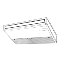
4. OUTLINES AND DIMENSIONS···········9
5. WIRING DIAGRAM····························13
6.
REFRIGERANT SYSTEM DIAGRAM
··14
7. MICROPROCESSOR CONTROL······15
8. TROUBLE SHOOTING······················22
9. DISASSEMBLY PROCEDURE··········29
10. PARTS LIST······································33
11. RoHS PARTS LIST ··························40
12. OPTIONAL PARTS ··························47
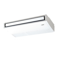
PCFY-P15NGMU-E
PCFY-P24NGMU-E
PCFY-P30NGMU-E
PCFY-P36NGMU-E
INDOOR UNIT
SPLIT-TYPE, HEAT PUMP AIR CONDITIONERS
August 2006
R410A
R22
No. OC343
REVISED EDITION-A
NOTE:
• This manual describes only
service data of the indoor
units.
• RoHS compliant products
have <G> mark on the spec
name plate.
• For servicing of RoHS
compliant products, refer to
the RoHS PARTS LIST.
Revision:
• RoHS PARTS LIST is added.
• Some descriptions have been
modified.
• Please void OC343.
[Models]
OC343A-1.qxp 06.8.2 11:31 AM Page 1

Questions and Answers:

Mitsubishi Electric City Multi PCFY-P15NGMU-E Specifications

General IconGeneral
BrandMitsubishi Electric
ModelCity Multi PCFY-P15NGMU-E
CategoryAir Conditioner
LanguageEnglish

Summary

Specifications

General Specifications

Provides detailed specifications for cooling, heating, electrical, dimensions, and noise.

Electrical Parts Specifications

Lists electrical components, their symbols, and specific ratings for each model.

Noise Criterion Curves

Presents octave band sound pressure levels for different fan speeds and frequencies.

Wiring Diagram

Legend and Wiring Diagram Overview

Explains symbols used in the wiring diagram and identifies key components.

Model-Specific Wiring Configurations and Settings

Illustrates wiring differences for models and switch settings.

Refrigerant System Diagram

Refrigerant Circuit and Sensor Locations

Diagrams the refrigerant circuit and locations of temperature sensors.

Required Pipe Sizes

Lists the required gas and liquid pipe diameters for different models.

Microprocessor Control

7-1. Cool Operation

Details thermoregulating, frozen prevention, and fan controls for cooling mode.

7-2. Dry Operation

Explains thermoregulating, fan, drain pump, and vane controls for dry mode.

7-3. Fan Operation

Describes drain pump and vane controls during fan-only operation.

7-4. Heat Operation

Covers thermoregulating, fan, drain pump, and vane controls for heating mode.

7-5. Auto Operation

Explains automatic switching between cool and heat modes based on temperature.

Trouble Shooting

8-1. How to Check Parts

Provides resistance checks for components like thermistors, fan motors, and vane motors.

Disassembly Procedure

Related product manuals