Do you have a question about the Mitsubishi Electric City Multi Series PCFY-P36NKMU-E and is the answer not in the manual?
| Brand | Mitsubishi Electric |
|---|---|
| Model | City Multi Series PCFY-P36NKMU-E |
| Category | Air Conditioner |
| Language | English |
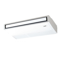
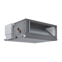
Identifies and describes the key components of the indoor unit.
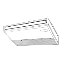
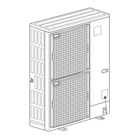
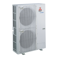
Dimensional and connection details for specific models.
Dimensional and connection details for specific models.
Dimensional and connection details for specific models.
Details thermostat and fan control logic during cooling mode.
Explains thermostat, fan, and drain pump control in dry mode.
Describes fan speed control and drain pump operation in fan-only mode.
Details thermostat, fan, hot adjust, and residual heat modes for heating.
Explains automatic mode changes and unit stop procedures.
Guides on how to check thermistors, motors, and switches for faults.
Provides characteristic graphs and operational summaries for thermistors and LEV.
Addresses issues with LEV operation, motor noise, and fan motor troubleshooting.
Step-by-step troubleshooting for the DC fan motor.
Explains DIP switch functions and address board settings for unit configuration.
Steps to remove the air intake grille, electrical box, and controller board.
Procedures for removing the room temperature thermistor and the fan motor assembly.
Instructions for removing side panels, fan assembly, and vane motor.
Steps to remove the under panel, drain pan, and pipe thermistors.
Procedures for removing the guide vane and the auto vane assembly.
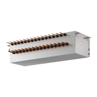
Procedures for disassembling the heat exchanger and linear expansion valve.