35
OCH610G
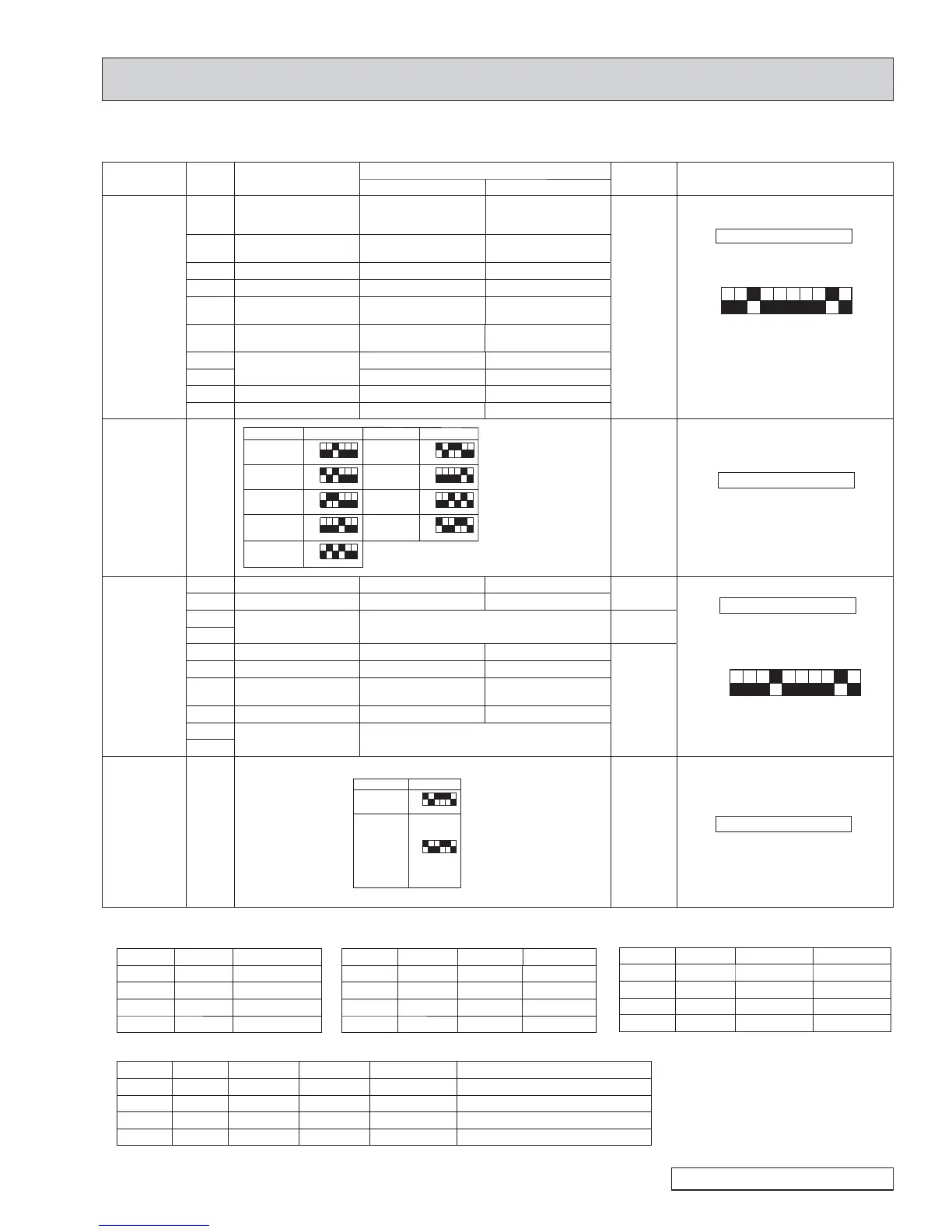
9-2. FUNCTION OF DIP SWITCH
7KHEODFNVTXDUHŶLQGLFDWHVDVZLWFKSRVLWLRQ
Switch Pole Function
Operation by switch
Effective
timing
Remarks
ON OFF
SW1
Function
Setting
1
Thermistor
<Room temperature
detection> position
Built-in remote
controller
Indoor unit
Under
suspension
Indoor controller board
ON
OFF
ON
OFF
1234567890
<Initial setting>
*
1
Fan operation at heating mode
*
2
Heat thermo-ON is operating.
*
3
Refer to the <Table A> below.
2
Filter clogging
detection
Provided Not provided
3 Filter cleaning 2,500h 100h
4 Fresh air intake Effective Not effective
5
Switching remote
indication
Thermo-ON signal
display
Indicating fan
operation ON/OFF
6 +XPLGL¿HUFRQWURO
Always operated while
the heat in ON*
1
Operated depends on
the condition*
2
7
$LUÀRZVHWLQFDVHRI
heat thermo-OFF
Low*
3
Extra low*
3
8 6HWWLQJDLUÀRZ
3
Depends on SW1-7
9 Auto restart function Effective Not effective
0
Power ON/OFF by breaker
Effective Not effective
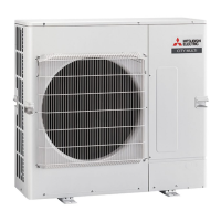
SW2
Capacity
code
setting
1–6
ON
OFF
123456
ON
OFF
123456
ON
OFF
123456
ON
OFF
123456
ON
OFF
123456
ON
OFF
123456
Capacity SW2 SW2
ON
OFF
123456
EP06NEMU-E EP24NEMU-E
EP30NEMU-E
EP36NEMU-E
EP48NEMU-E
EP08NEMU-E
EP12NEMU-E
EP15NEMU-E
EP18NEMU-E(1)
ON
OFF
123456
ON
OFF
123456
Capacity
Before
power
supply
ON
Indoor controller board
<Initial setting>
Set for each capacity.
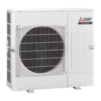
SW3
Function
setting
1
Heat pump/Cooling only
Cooling only Heat pump
Under
suspension
Indoor controller board
<Initial setting>
Set for each capacity.
ON
OFF
1234567890
*
4
Refer to the <Table C> below for
SW3-5 and SW-3-6.
2 /RXYHU+XPLGL¿HU ——
3
3D i-see Sensor
positioning
Depending on the combination of SW3-3
and SW3-4. Refer to the <Table B> below.
Before power
supply ON
4
5
Vane horizontal angle
1
Second setting*
4
First setting*
4
Under
suspension
6
Vane horizontal angle
2
Third setting*
4
Depends on SW3-5
7
Changing the opening of
linear expansion valve
Effective Not effective
8
Sensible temperature correction
Not effective Effective
9
3D i-see Sensor
ceiling height setting
Depending on the combination of SW3-9
and SW3-10. Refer to the <Table D> below.
0
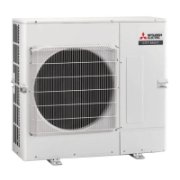
SW4
Model selection
1–6
Before
power
supply
ON
Indoor controller board
Service controller board only
<Table A>
SW1-7 SW1-8
OFF OFF Extra low
ON OFF Low
OFF ON 6HWWLQJDLUÀRZ
ON ON stop
Continue to the next page
ON
OFF
123456
Capacity SW4
ON
OFF
123456
EP06NEMU-E
EP24NEMU-E
EP30NEMU-E
EP36NEMU-E
EP48NEMU-E
EP08NEMU-E
EP12NEMU-E
EP15NEMU-E
EP18NEMU-E
EP18NEMU-E1
<Table B>
SW3-3 SW3-4 Initial setting
OFF OFF Position
1
ON OFF Position
2
OFF ON Standard Ɣ
ON ON (Standard)
<Table C>
SW3-5 SW3-6
Vane setting Initial setting
Setting Vane position
OFF OFF Setting
1
Ɣ Standard Standard
ON OFF Setting
2
Less draft*
5
Upward position than the standard
OFF ON Setting
3
Less smudging
Downward position than the standard
ON ON Unused ņņ
<Table D>
SW3-9 SW3-10 Initial setting
OFF OFF Low ceiling
ON OFF Standard Ɣ
OFF ON High ceiling
ON ON (High ceiling)
*
5
Be careful of the smudge on ceiling.