AIR CONDITIONERS CITY MULTI
Models PUHY-200YMF-B, 250YMF-B
PUHY-P200YMF-B, P250YMF-B
PUY-200YMF-B, 250YMF-B
PURY-200YMF-B, 250YMF-B
PURY-P200YMF-B, P250YMF-B
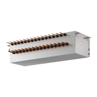
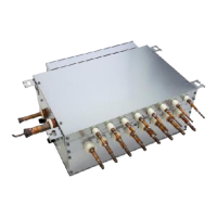
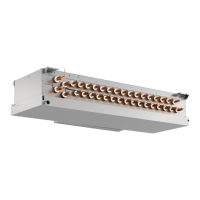
CMB-P104, P105, P106, P108, P1010V-D
CMB-P104, P105, P106, P108, P1010, P1013, P1016V-E
Service Handbook
Service Handbook PUHY-200YMF-B, 250YMF-B
PUHY-P200YMF-B, P250YMF-B
PUY-200YMF-B, 250YMF-B
PURY-200YMF-B, 250YMF-B
PURY-P200YMF-B, P250YMF-B
CMB-P104, P105, P106, P108, P1010V-D
CMB-P104, P105, P106, P108, P1010, P1013, P1016V-E
HEAD OFFICE MITSUBISHI DENKI BLDG. MARUNOUCHI TOKYO 100-0005 TELEX J24532 CABLE MELCO TOKYO
Issued in June 1999 MEE98K028
Printed in Japan
New publication effective June 1999
Specifications subject to change without notice.
Service Handbook PUHY, PUY, PURY-200·250YMF-B/PUHY, PURY-P200·P250YMF-B/CMB-P-V-D, CMB-P-V-E