EasyManua.ls Logo

Mitsubishi Electric CMB-WP1016V-GA1 User Manual

Mitsubishi Electric CMB-WP1016V-GA1
294 pages
To Next Page IconTo Next Page
Page #1 background imageLoading...
Page #1 background image

Table of Contents

Question and Answer IconNeed help?

Do you have a question about the Mitsubishi Electric CMB-WP1016V-GA1 and is the answer not in the manual?

Mitsubishi Electric CMB-WP1016V-GA1 Specifications

General IconGeneral
BrandMitsubishi Electric
ModelCMB-WP1016V-GA1
CategoryAir Conditioner
LanguageEnglish

Summary

Safety Precautions

General Safety Guidelines and Warnings

Covers essential safety points for installation, operation, and handling, including specific hazards like refrigerant leaks and physical dangers.

Refrigerant and Electrical Safety

Covers refrigerant type, installation, wiring, electrical work, and component safety measures.

Precautions for Handling R410A Units

R410A Specific Handling, Piping, and Tool Requirements

Details piping materials, tool selection, and specific handling procedures for R410A refrigerant.

Installation and Electrical Work Precautions

Electrical Safety, Grounding, and Circuit Protection

Covers proper grounding, power supply wire selection, and circuit protection devices.

Test Run Precautions

Pre-Operation Checks and Procedures

Covers essential steps before starting a test run, including component checks and system readiness.

I Read Before Servicing

Initial Checks, Safety, and Tool Preparation

Covers essential pre-service checks, safety guidelines, and tool gathering.

Necessary Tools and Materials for R410A

R410A Specific Tool Requirements and Prohibitions

Lists exclusive, restricted, prohibited, and compatible tools for R410A.

R410A Piping Materials and Specifications

Copper Pipe Requirements and Types for R410A

Details copper pipe materials, radial thickness, and types.

Brazing Procedures for R410A Systems

Brazing Best Practices and Rationale

Outlines critical observations and explains the rationale behind brazing methods.

Air Tightness Test for Refrigerant Circuit

Test Method, Nitrogen Use, and Leak Detection Notes

Details test procedures, nitrogen use, and leak detection considerations.

Vacuum Drying (Evacuation) Procedures

Vacuum Pump, Gauge, and Evacuation Time Requirements

Specifies necessary equipment and evacuation duration.

Refrigerant Charging and Leak Remedies

R410A Charging Method and Leak Response Procedures

Explains charging procedures and how to handle leaks.

Refrigerating Machine Oil Requirements

Oil Type and Contaminant Effects in HFC Systems

Details oil types and the impact of contaminants on the refrigeration cycle.

II Restrictions

System Configuration and Unit Combinations

Details compatible outdoor and indoor units for system setup.

M-NET Address Settings

M-NET Address Configuration Table and Methods

Provides a comprehensive table for setting M-NET addresses for system components.

Wiring Methods and Address Settings

Address Setting Method and Procedures

Step-by-step guide for setting component addresses.

IV Electrical Wiring Diagrams

HBC Controller and Sub-HBC Wiring Diagram

Provides the detailed wiring schematic for the HBC and Sub-HBC.

Transmission Booster Electrical Wiring Diagram

Transmission Booster Wiring Schematic

Provides the wiring diagram for the transmission booster.

V Refrigerant Circuit

Refrigerant Circuit Diagram Overview

General diagram of the refrigerant system.

Refrigerant Circuit Diagrams

HBC Controller Refrigerant Circuit Details

Specific refrigerant flow for the HBC controller.

Principal Parts and Functions

HBC Controller Key Components and Usage

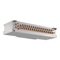
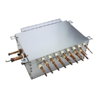
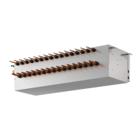
Describes major parts of the HBC controller and their functions.

VI Control

Dipswitch Functions and Settings

Explains the functions and factory settings of dipswitches.

HBC Controller Operation and Control Logic

Details how to operate and control the HBC controller.

Dipswitch Functions and Settings

SW3, SW4, and SW5 Dipswitch Functions

Explains the functions of SW3, SW4, and SW5 dipswitches.

Controlling the HBC Controller

Water Pump and Valve Control Logic

Explains control logic for water pumps and valves.

Heat Exchanger and Defrost Control Logic

Details control logic for heat exchangers and defrost operations.

VII Test Run Mode

Pre-Test Run Checks and Preparations

Lists items to check before starting a test run.

Refrigerant Amount Analysis and Adjustment

Covers analyzing operating characteristics and adjusting refrigerant.

VIII Troubleshooting

Comprehensive Error Code Lists

Lists all error codes with definitions and applicable units.

Troubleshooting Error Displays

Responding to Remote Controller Error Messages

Guide to interpreting and resolving remote controller errors.

Troubleshooting Specific Error Codes

Drain Sensor, Water Pump, and Pressure Sensor Errors

Details troubleshooting for drain, pump, and pressure sensor related errors.

Temperature Sensor Fault Error Codes

Lists and explains error codes for temperature sensor failures.

ACCT Sensor, High-Pressure Sensor, and Power Supply Errors

Covers troubleshooting for ACCT, high-pressure sensor, and power supply errors.

Communication and Signal Sync Error Codes

Details troubleshooting for communication and signal sync issues.

Troubleshooting Error Code 2500 (Drain Sensor/Pump Faults)

Drain Sensor Submergence Troubleshooting

Addresses causes and remedies for drain sensor submergence errors.

Drain Pump Fault (Float Switch) Troubleshooting

Addresses causes and remedies for drain pump faults related to float switches.

Troubleshooting Error Code 2501 (Water Pump Fault)

Water Pump Fault Troubleshooting Steps

Details causes and remedies for water pump malfunctions.

Troubleshooting Error Code 2502 (Drain Pump Fault)

Drain Pump Fault (Sensor) Troubleshooting Steps

Addresses causes and remedies for sensor-related drain pump faults.

Drain Pump Fault (Float Switch) Troubleshooting Steps

Addresses causes and remedies for float switch related drain pump faults.

Troubleshooting Error Code 2503 (Drain Sensor Fault)

Drain Sensor (Thermistor) Fault Troubleshooting Steps

Details causes and remedies for drain sensor thermistor faults.

Troubleshooting Error Code 4102 (Open Phase)

Troubleshooting Error Code 4106 (Transmission Power Supply Fault)

Troubleshooting Temperature Sensor Faults (Codes 5111-5178)

Troubleshooting High-Pressure Sensor Fault (Code 5201)

Troubleshooting ACCT Sensor Faults (Codes 5301)

Troubleshooting Transmission Processor Hardware Error (Code 6602)

Troubleshooting No ACK Error (Code 6607) - Single Unit Systems

Troubleshooting No ACK Error (Code 6607) - Multiple Unit Systems

Troubleshooting Total Capacity Error (Code 7100)

Troubleshooting Capacity Code Setting Error (Code 7101)

Troubleshooting Wrong Number of Connected Units Error (Code 7102)

Remote Controller Malfunction Troubleshooting (MA)

Investigation of Transmission Wave Shape/Noise

Troubleshooting Principal Parts

Troubleshooting Flow Chart for LEV, Solenoid Valve, and Valve Block

Troubleshooting Temperature Sensors

Troubleshooting Transmission Power Circuit

[5] Refrigerant Leak

Locating Refrigerant Leaks in Cooling Season

Procedures for finding leaks in extension pipes, HBC controllers, and outdoor units during cooling.

Refrigerant Leak Detection and Repair

Locating Refrigerant Leaks in Heating Season

Procedures for finding leaks in extension pipes, HBC controllers, and outdoor units during heating.

Water Pump Replacement Procedure

Instructions for Water Pump Replacement

IX LED Monitor Display on the Outdoor Unit Board

How to Read Outdoor Unit LEDs on Service Monitor

Explains how to interpret LED displays on the service monitor.

HBC Controller/Sub-HBC Board LED Display

Explains how to read LEDs on the HBC/Sub-HBC boards.

LED Monitor Display on the Outdoor Unit Board

Outdoor Unit Board LED Display Interpretation

Explains how to read outdoor unit board LEDs.

Related product manuals