Do you have a question about the Mitsubishi Electric CMB-P1016V-E and is the answer not in the manual?
Guidance on storing refrigerant piping to prevent contamination and maintain quality.
Instructions for preparing refrigerant piping, including oil application for connections.
Visual identification and labeling of major parts within the outdoor unit assembly.
Refrigerant circuit diagram and thermal sensor locations for specific PUHY models.
Refrigerant circuit diagram and thermal sensor locations for specific PUY models.
Refrigerant circuit diagram and thermal sensor locations for specific PUHY-P models.
Refrigerant circuit diagram and thermal sensor locations for specific PURY models.
Refrigerant circuit diagram and thermal sensor locations for specific PURY-P models.
Identification of outdoor unit models and their configurations.
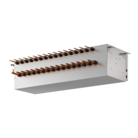
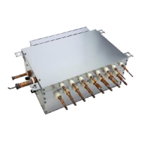
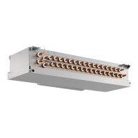
Information on BC controller models and their associated branch pipe kits.
Details on various branch pipe and joint pipe kits for system configuration.
List of indoor unit models, capacities, and types available.
Information on optional decorative panels for indoor units.
Identification of various remote controller models used with the system.
Electrical wiring diagram specific to PU(H)Y-(P) models.
Electrical wiring diagram specific to PURY-(P) models.
Standard operational data for cooling mode, including ambient and sectional temperatures.
Standard operational data for heating mode, including ambient and sectional temperatures.
Configuration settings for outdoor unit switches (SWU, SW1, SW2, SW3, SW4).
Configuration settings for indoor unit DIP switches (SW1, SW3, SW2).
Essential checks and precautions to perform before initiating a test run.
Step-by-step guide for conducting a test run and verifying system operations.
Checks to perform from installation to test run for system structure verification.
Operational flow for the outdoor unit, including modes and error handling.
Operational flow chart for the BC controller specific to PURY models.
Operational flow chart detailing the logic for indoor unit operations and states.
Flowchart detailing the operational sequence during cooling mode.
Flowchart detailing the operational sequence during heating mode.
Flowchart illustrating the operational sequence during dry operation mode.
Function and specifications of the compressor.
Function and specifications of the high pressure sensor.
Function and specifications of the low pressure sensor.
Function and specifications of the pressure switch.
Function and specifications of various thermistors.
Function and specifications of solenoid valves.
Function and specifications of linear expansion valves.
Function and specifications of the liquid level detection heater.
Function and specifications of various thermistors.
Function and specifications of pressure sensors.
Explains the relationship between refrigerant amount and system performance.
Methods for judging and adjusting refrigerant levels based on symptoms and self-diagnosis.
Troubleshooting steps focusing on major components like sensors and valves.
Common symptoms and error codes associated with noise on the transmission line.
Procedure for confirming transmission wave shape using an oscilloscope.
Specific actions to mitigate noise interference in transmission lines.
Troubleshooting steps for low wave height and 'HO' state issues.
Flowchart and steps for troubleshooting pressure sensors.
Procedure for removing the service panel to access internal components.
Procedure for accessing and checking components within the BC controller's control box.
Procedure for checking and replacing thermistors for temperature detection.
Procedure for checking and replacing pressure sensors.
Procedure for replacing applicable LEV units.
Procedure for removing and servicing solenoid valve coils.
Explanation of DIP switch settings and their relation to LED displays for operating conditions.
Steps for finding leaks in extension piping or indoor units during cooling operation.
Steps for finding leaks in extension piping or indoor units during heating operation.
Procedure for locating and repairing leaks in the outdoor unit during heating operation.
| Category | Air Conditioner |
|---|---|
| Refrigerant | R410A |
| Indoor Unit Noise Level | N/A (depends on connected indoor units) |
| Indoor Unit Dimensions (WxHxD) | N/A (depends on connected indoor units) |
| Indoor Unit Weight | N/A (depends on connected indoor units) |