Q
qhoffmanAug 6, 2025
What to do if my Mitsubishi Electric Air Conditioner pressure sensor reading doesn't change?
- MMark SwansonAug 6, 2025
If the pressure reading in the LD1 display does not change, the affected pressure sensor is faulty.
What to do if my Mitsubishi Electric Air Conditioner pressure sensor reading doesn't change?
If the pressure reading in the LD1 display does not change, the affected pressure sensor is faulty.
What to do if my Mitsubishi Electric CMB-P108 pressure is too high?
If the pressure is 3.14MPa (in the case of the low pressure sensor, 0.98MPa) or higher, the MAIN board is faulty.
What to do if my Mitsubishi Electric CMB-P108 pressure sensor shows 3.14MPa?
If the pressure according to the LD1 display is 3.14MPa (in the case of the low pressure sensor, 0.98MPa) or higher, the affected pressure sensor is faulty.
What to do if my Mitsubishi Electric CMB-P108 pressure is 0~0.098MPa?
If the pressure is 0~0.098MPa on the LD1 display, the affected pressure sensor is faulty.
Why is the internal pressure dropping in my Mitsubishi Electric CMB-P108 Air Conditioner?
If the gauge pressure is 0~0.098MPa, it indicates the internal pressure is dropping due to gas leakage. Check for failure by comparing the sensing pressure.
What to do if my Mitsubishi Electric CMB-P108 Air Conditioner pressure sensors differ by more than 0.098MPa?
If the difference between the two pressures exceeds 0.098MPa, the affected pressure sensor is faulty (deteriorating performance).
| Brand | Mitsubishi Electric |
|---|---|
| Model | CMB-P108 |
| Category | Air Conditioner |
| Language | English |
Lists required tools for installation and servicing of the unit.
Covers pipe types, thickness, storage guidelines, and preparation steps.
Details on pipe joining, leak testing, and system evacuation for refrigerant circuits.
Explains R410A properties, notes on refrigerating machine oil, and contamination effects.
Defines allowable cable types, lengths, and system connection examples.
Details on configuring unit switches, addresses, and remote controller setups.
Specifies allowable lengths and diameters for refrigerant piping based on model.
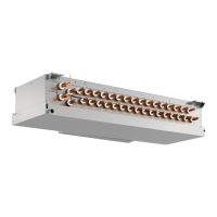
Identifies major parts of the heat source unit and its refrigerant flow.
Describes the heat source unit's control box and circuit boards.
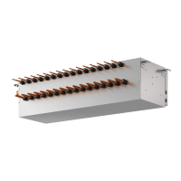
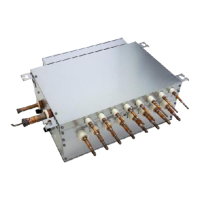
Details internal components of BC controllers and their circuit boards.
Compares features, specifications, and selection criteria for remote controllers.
Explains group settings, interlocks, and temperature sensor usage.
Provides detailed electrical wiring schematics for the heat source unit.
Details wiring schematics for the BC controller.
Illustrates refrigerant flow for PQHY and PQRY heat source units.
Describes the role and specifications of major components in the refrigerant circuit.
Details dipswitch functions, initial control, bypass, and compressor frequency management.
Explains control logic for solenoid valves, expansion valves, and operation modes.
Visualizes the logic for determining unit operation modes.
Lists essential checks and preparation steps before conducting a test run.
Guides on performing test runs and adjusting refrigerant amounts.
Provides typical operating values for performance verification.
Reference for error codes and guidance on responding to remote controller messages.
Detailed diagnostic steps for sensors, valves, and control boards.
Procedures for fixing refrigerant leaks and maintaining the BC controller.
Explains how to read the service monitor and interpret LED codes.
Describes time tracking, error history storage, and initial display information.
Comprehensive reference for LED codes indicating various operational data.