73
DISASSEMBLY PROCEDURE
PHOTOS/ FIGURES
Photo 3-3
3. How to remove the electrical parts
(Steps (1) through (3) are applied to all the following parts.)
(1) Remove the front panel. (Refer to Procedure 1).
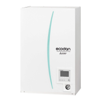
(2) Remove the 3 screws holding the control box. (Photo
3-1)
(3) Slightly lift and pull out the control box. (Photo 3-1)
<Earth leakage circuit breaker> (Photo 3-2)
(4) Disconnect all the lead wires from the earth leakage cir-
cuit breaker.
(5) Remove the 2 screws on the earth leakage circuit break-
er.
Note: To avoid dropping of the breaker, hold the breaker by
hand when removing the last screws.
<Contactor> (Photo 3-2)
(4) Disconnect all the lead wires from the contactors.
(5) Remove the 2 screws on each contactor.
Note: To avoid dropping of the contactors, hold the contac-
tors by hand when removing the last screws.
To prevent an electrical shock, wait until all the LED
lamps on the FTC control board are turned off.
<Terminal block> (Photo 3-2)
(4) Disconnect all the lead wires from the terminal block. (To
disconnect the S1, S2 and S3 lead wires, disengage the
locks by pressing on the claws.)
(5) Remove the screw on the terminal block.
Note: To avoid dropping of the terminal block, hold the termi-
nal block by hand when removing the screw .
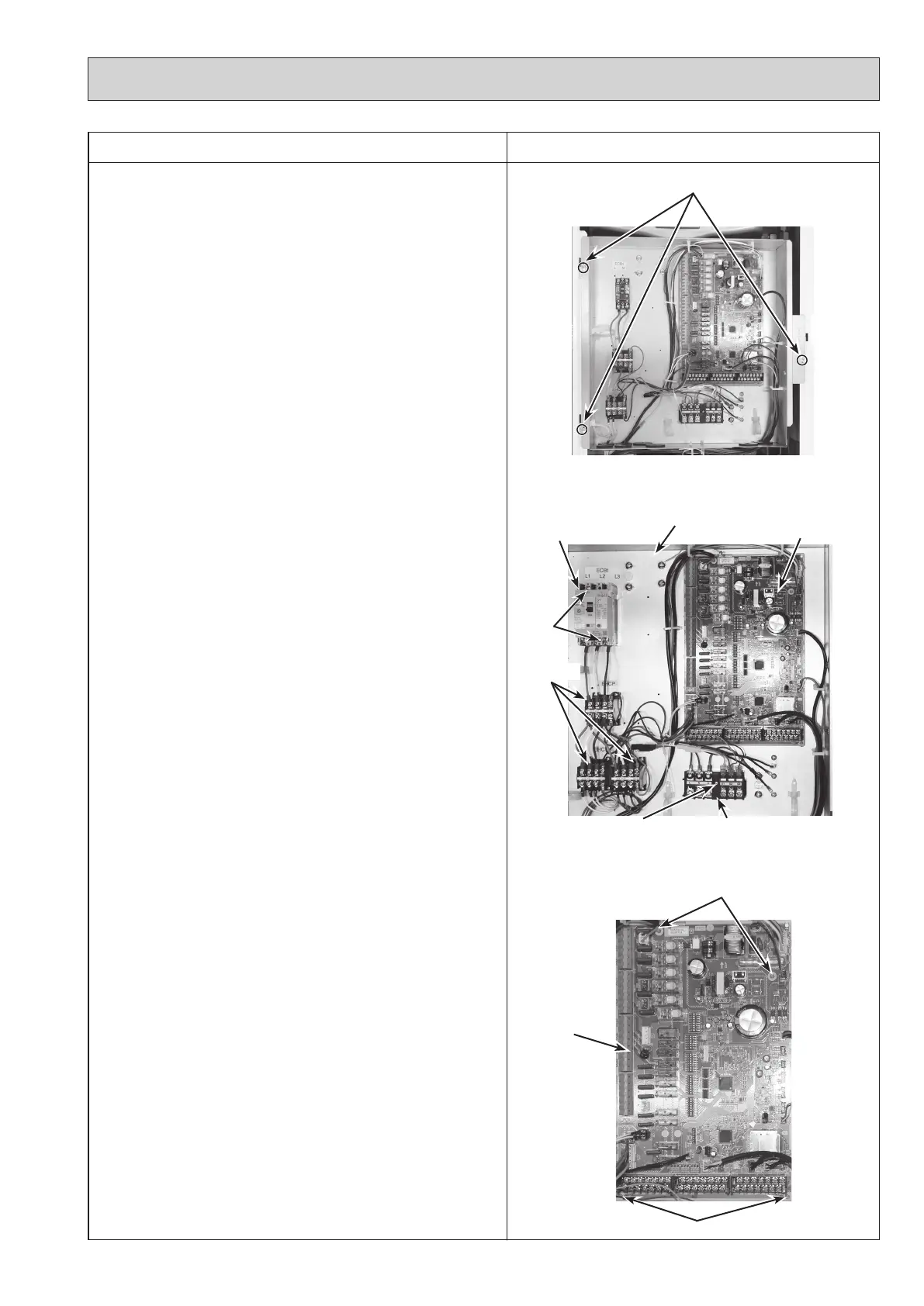
<Controller board> (Photo 3-3)
(4) Disconnect all the lead wires from the controller board.
(5) Remove the controller board from the 4 board supports.
Photo 3-2
* The photos shown are of the EHSC-YM9C model.
Terminal block (TB1)
Earth leakage circuit
breaker (ECB1)
Contactors
Control box
Controller
board
Screw
Photo 3-1
Control box fixing screws
Controller
board
Screws
Board supports
Board supports
OCH571D
 Loading...