EasyManua.ls Logo

Mitsubishi Electric F700 - User Manual

Mitsubishi Electric F700
303 pages
Print Icon
To Next Page IconTo Next Page
Loading...
INSTRUCTION MANUAL (Applied)
INVERTER
INVERTER FR-F700 INSTRUCTION MANUAL (Applied)
D
IB-0600177ENG-D (0607)MEE Printed in Japan Specifications subject to change without notice.
HEAD OFFICE:TOKYO BLDG MARUNOUCHI TOKYO 100-8310
3
PRECAUTIONS FOR USE
OF THE INVERTER
4
PARAMETERS
5
PROTECTIVE FUNCTIONS
6
PRECAUTIONS FOR
MAINTENANCE AND INSPECTION
7
SPECIFICATIONS
WIRING
OUTLINE
2
1
FR-F720-0.75K to 110K
FR-F740-0.75K to 560K

Table of Contents

Questions and Answers

  • M
    Matthew DixonAug 19, 2025
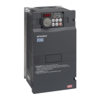
    What to do if Mitsubishi Electric F700 shows fin overheat?
    • J
      Justin BlackAug 19, 2025
      If your Mitsubishi Electric Inverter displays a fin overheat error, it means the heatsink has overheated, triggering the temperature sensor to shut off the inverter output. Here's what you can do: 1. Ensure the ambient temperature is within the specified limits. 2. Clean the heatsink to remove any dust or obstructions. 3. Consider replacing the cooling fan.
  • E
    eharrisAug 21, 2025
    What to do if Mitsubishi Electric F700 Inverter shows input phase failure?
    • A
      Angela WalkerAug 22, 2025
      If your Mitsubishi Electric Inverter shows an input phase failure alarm, it means that when the function valid setting (=1) is set in Pr. 872 Input phase failure protection selection, one phase of the three phase power input opens. You can try the following: * Check and properly wire the cables. * Repair any breaks in the cable. * Verify the Pr. 872 Input phase failure protection selection setting.
  • M
    mannsamanthaAug 25, 2025
    Why Mitsubishi Electric Inverter shows regenerative overvoltage shut-off during acceleration?
    • S
      shannongrahamAug 25, 2025
      If a regenerative overvoltage shut-off occurs during acceleration with your Mitsubishi Electric Inverter, it indicates that regenerative energy is causing the inverter's internal main circuit DC voltage to exceed the specified value, activating the protective circuit. To resolve this: * Decrease the acceleration time. * Utilize the regeneration avoidance function (Pr. 882 to Pr. 886).
  • L
    lintammyAug 26, 2025
    What to do if Mitsubishi Electric F700 displays fan fault?
    • E
      Erika BrownAug 27, 2025
      If your Mitsubishi Electric Inverter displays a fan fault, it signifies that the cooling fan has stopped due to a fault or operates differently from the setting of Pr. 244 Cooling fan operation selection. Check for a fan fault and please contact your sales representative.
  • D
    danielle87Aug 28, 2025
    Why Mitsubishi Electric F700 shows regenerative brake prealarm?
    • S
      Scott BrownAug 28, 2025
      The regenerative brake prealarm on your Mitsubishi Electric Inverter appears when the regenerative brake duty reaches or exceeds 85% of the Pr. 70 Special regenerative brake duty value. To address this: * Increase the deceleration time. * Check the Pr. 30 Regenerative function selection and Pr. 70 Special regenerative brake duty values.
  • R
    Rachael SmithAug 30, 2025
    Why Mitsubishi Electric Inverter shows regenerative overvoltage shut-off during constant speed?
    • L
      Lynn JacksonAug 30, 2025
      If regenerative overvoltage shut-off occurs during constant speed with your Mitsubishi Electric Inverter, it means regenerative energy is causing the inverter's internal main circuit DC voltage to exceed the specified value, activating the protective circuit. Keep the load stable to resolve this.
  • C
    Crystal FloresSep 1, 2025
    What to do if Mitsubishi Electric F700 shows stall prevention?
    • A
      acurtisSep 1, 2025
      If the frequency has fallen to 0.5Hz by stall prevention operation and remains for 3s, an alarm (E.OLT) appears to shutoff the Mitsubishi Electric Inverter output. Reduce the load weight.
  • B
    Benjamin ParkerSep 3, 2025
    Why Mitsubishi Electric F700 displays parameter write error?
    • T
      Thomas ReynoldsSep 3, 2025
      A parameter write error on your Mitsubishi Electric Inverter can occur due to a few reasons: 1. You attempted to perform a parameter copy write during operation. After stopping operation, make parameter copy again. 2. An error occurred in the EEPROM on the operation panel side during parameter copy writing. Check for an operation panel (FR-DU07) failure. Please contact your sales representative.
  • C
    carrjosephSep 6, 2025
    What causes communication error on Mitsubishi Electric F700?
    • K
      Kevin GrossSep 6, 2025
      A communication error on your Mitsubishi Electric Inverter occurs when communication errors happen consecutively for more than the permissible retry count. This happens when a value other than "9999" is set in Pr. 335 RS-485 communication retry count during RS-485 communication from the RS-485 terminals. Perform wiring of the RS-485 terminals properly.
  • J
    Jeremy LopezSep 8, 2025
    What does analog input error mean on Mitsubishi Electric Inverter?
    • I
      ihunterSep 8, 2025
      An analog input error on your Mitsubishi Electric Inverter appears when 30mA or more is input, or a voltage (7.5V or more) is input with the terminal 2/4 set to current input. Either give a frequency command by current input or set Pr. 73 Analog input selection or Pr. 267 Terminal 4 input selection.

Summary

OUTLINE

Product checking and parts identification

Instructions for unpacking and verifying the inverter and its capacity plate.

Inverter and peripheral devices

Details on the inverter and associated peripheral devices like power supply and PLC.

Method of removal and reinstallation of the front cover

Step-by-step guide for removing and reinstalling the inverter's front cover.

Installation of the inverter and enclosure design

Considerations for designing and manufacturing inverter enclosures, including environmental factors.

WIRING

Terminal connection diagram

Diagram illustrating the terminal connections for the main and control circuits.

EMC filter

Explanation of the built-in EMC filter and its ON/OFF settings.

Main circuit terminal specifications

Specifications for the main circuit terminals, including AC power input and inverter output.

Cables and wiring length

Recommendations for cable size and wiring length to ensure proper voltage drop and torque.

PRECAUTIONS FOR USE OF THE INVERTER

Noise and leakage currents

Discussion on noise and leakage currents, their causes, and countermeasures.

Power supply harmonics

Explanation of power supply harmonics generated by the inverter and suppression techniques.

Harmonic suppression guideline

Guidelines for harmonic suppression to protect consumers from outgoing harmonic currents.

Installation of a reactor

Guidance on installing AC or DC reactors to prevent excessive peak current.

Inverter-driven 400 V class motor

Measures to address surge voltage issues when driving 400V class motors.

Precautions for use of the inverter

General precautions for handling and operating the inverter to prevent damage or shortened lifespan.

PARAMETERS

Operation panel (FR-DU07)

Description of the parts and basic operation of the FR-DU07 operation panel.

Parameter List

Comprehensive list of inverter parameters with their names, ranges, and descriptions.

Adjust the output torque of the motor (current)

Methods to adjust motor output torque, including manual torque boost and magnetic flux vector control.

Limit the output frequency

Procedures for setting maximum/minimum output frequencies and avoiding mechanical resonance points.

Set V;F pattern

Guidelines for setting V/F patterns, including base frequency, voltage, and load patterns.

Frequency setting by external terminals

How to set frequency using external terminals, including multi-speed and jog operations.

Setting of acceleration;deceleration time and acceleration;deceleration pattern

Configuration of acceleration/deceleration times and patterns, including starting frequency.

Selection and protection of a motor

Details on motor protection features like thermal relay and applied motor settings.

Motor brake and stop operation

Methods for motor braking and stopping, including DC injection brake and regenerative brake.

Function assignment of external terminal and control

Mapping input/output terminals to various functions and control logic.

Monitor display and monitor output signal

How to configure and use monitor displays and output signals for various parameters.

Misoperation prevention and parameter setting restriction

Settings to prevent misoperation, including parameter write protection and PU disconnection.

Energy saving operation and energy saving monitor

Features for energy saving control and monitoring of power consumption.

Motor noise, noise reduction

Techniques to reduce motor noise by adjusting PWM carrier frequency and Soft-PWM control.

Frequency setting by analog input (terminal 1, 2, 4)

Configuration of analog inputs for frequency setting and compensation.

Misoperation prevention and parameter setting restriction

Settings to prevent misoperation, including parameter write protection and PU disconnection.

Selection of operation mode and operation location

Guidelines for selecting operation modes and controlling the inverter via terminals or communication.

PROTECTIVE FUNCTIONS

Reset method of protective function

Procedure for resetting protective functions and handling alarms and warnings.

List of alarm display

Table listing operation panel indications for errors, warnings, and major faults with referenc

Causes and corrective actions

Troubleshooting guide for common error messages, including descriptions and corrective actions.

PRECAUTIONS FOR MAINTENANCE AND INSPECTION

Inspection item

General inspection items to prevent faults, including daily checks.

Daily and periodic inspection

Detailed inspection checklist for various components and environmental conditions.

Display of the life of the inverter parts

How to check the estimated life of inverter components like capacitors and cooling fans.

Checking the inverter and converter modules

Procedure for checking inverter and converter modules using a tester.

Cleaning

Guidelines for cleaning the inverter unit to maintain its performance.

Replacement of parts

Information on periodically replacing parts like cooling fans and capacitors.

SPECIFICATIONS

Rating

Detailed rating specifications for 200V and 400V class inverters, including capacity and current.

Common specifications

General specifications covering control methods, frequency accuracy, and protective functions.

Outline dimension drawings

Physical dimensions and mounting hole details for various inverter models.

Heatsink protrusion attachment procedure

Instructions for installing the inverter with heatsink protrusion for improved heat dissipation.

Mitsubishi Electric F700 Specifications

General IconGeneral
BrandMitsubishi Electric
ModelF700
CategoryInverter
LanguageEnglish

Related product manuals