M
Michael GarciaNov 22, 2025
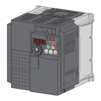
How to fix overcurrent trip during acceleration on Mitsubishi Electric FR-E720-1.5K?
- KkennedyaustinNov 22, 2025
If the Mitsubishi Electric Inverter experiences an overcurrent trip during acceleration, it means that an overcurrent has occurred. To resolve this, try the following: * Increase the acceleration time. * Check for output short circuits or ground faults in the wiring. * If 'E.OC1' appears consistently at start, disconnect and restart the inverter. If the problem persists, the inverter may be faulty and you should contact your sales representative. * Ensure the base frequency is correctly set (Pr. 3) for your motor (50Hz). * Reduce the stall prevention operation level and activate both stall prevention and fast-response current limit operations (Pr.156). * For regenerative driving, adjust the base voltage in Pr. 19. * If the motor is coasting, stop it before issuing a start co...