EasyManua.ls Logo

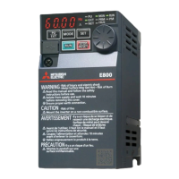
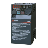
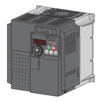
Mitsubishi Electric FR-E840-0016 User Manual

Mitsubishi Electric FR-E840-0016
534 pages
To Next Page IconTo Next Page
Page #1 background imageLoading...
Page #1 background image
INVERTER
INVERTER FR-E800 Instruction Manual (Function)
D
HEAD OFFICE: TOKYO BUILDING 2-7-3, MARUNOUCHI, CHIYODA-KU, TOKYO 100-8310, JAPAN
IB(NA)-0600868ENG-D(2010)MEE Printed in Japan Specifications subject to change without notice.
FR-E800
Instruction Manual (Function)
FR-E820-0008(0.1K) to 0330(7.5K)
FR-E840-0016(0.4K) to 0170(7.5K)
FR-E860-0017(0.75K) to 0120(7.5K)
FR-E820S-0008(0.1K) to 0110(2.2K)
FR-E820-0008(0.1K) to 0330(7.5K)E
FR-E840-0016(0.4K) to 0170(7.5K)E
FR-E860-0017(0.75K) to 0120(7.5K)E
FR-E820S-0008(0.1K) to 0110(2.2K)E
FR-E820-0008(0.1K) to 0330(7.5K)SCE
FR-E840-0016(0.4K) to 0170(7.5K)SCE
FR-E860-0017(0.75K) to 0120(7.5K)SCE
FR-E820S-0008(0.1K) to 0110(2.2K)SCE
Compact, high functionality inverters
Model
FR-E800 Instruction
Manual (Function)
Model code 1A2-P91

Table of Contents

Other manuals for Mitsubishi Electric FR-E840-0016

Question and Answer IconNeed help?

Do you have a question about the Mitsubishi Electric FR-E840-0016 and is the answer not in the manual?

Mitsubishi Electric FR-E840-0016 Specifications

General IconGeneral
BrandMitsubishi Electric
ModelFR-E840-0016
CategoryInverter
LanguageEnglish

Summary

Chapter 1 Introduction

1.1 Inverter model

Details on how to identify the inverter model by checking the rating plate, covering voltage class, phase, capacity, and communication type.

Chapter 2 Basic Operation

2.1 Operation panel

Description of the components of the operation panel, including monitor, LEDs, keys, and USB connector for standard and Ethernet models.

2.5 Basic operation procedure (PU operation)

Step-by-step guide for basic PU operation, including setting frequency, starting, and stopping the inverter.

2.6 Basic operation procedure (External operation)

Procedure for basic external operation, covering setting frequency via operation panel, switches, and analog signals.

Chapter 3 Parameters

3.2 Parameter list (by parameter number)

Comprehensive list of inverter parameters, including function, Pr. number, name, setting range, and reference page.

Chapter 4 Control Method

4.1 Vector control and Real sensorless vector control

Explanation of Vector control and Real sensorless vector control techniques, including equivalent circuits and advantages.

4.2 Changing the control method and mode

Guide on setting control methods (V/F, vector, sensorless) and control modes (speed, torque, position) using parameters.

4.3 Selecting the Advanced magnetic flux vector control

Procedure for selecting Advanced magnetic flux vector control, including motor settings and auto tuning.

4.4 Selecting the PM sensorless vector control

Instructions for initializing parameters for PM sensorless vector control and setting the PM motor.

Chapter 5 Speed Control

5.1 Setting procedure of Real sensorless vector control (speed control)

Step-by-step guide for setting Real sensorless vector control for speed control, including wiring, parameters, and test operation.

5.2 Setting procedure of Vector control (speed control)

Procedure for setting Vector control (speed control), covering wiring, motor settings, and test operation.

5.3 Setting procedure of PM sensorless vector control (speed control)

Instructions for setting PM sensorless vector control for speed control, including parameter configuration and test operation.

5.4 Setting the torque limit level

Guide to limiting the output torque to prevent overspeeding, covering parameter settings and analog input methods.

5.5 Performing high-accuracy, fast-response control (gain adjustment)

Explanation of gain adjustment for high-accuracy and fast-response control, including speed and torque control gain adjustments.

5.8 Avoiding motor overrunning

Methods to prevent motor overrunning due to excessive load torque or incorrect encoder settings, including speed deviation excess detection.

Chapter 6 Torque Control

6.1 Torque control

Explanation of torque control operation, including controlling output torque as commanded and preventing motor overspeeding.

6.2 Setting procedure of Real sensorless vector control (torque control)

Step-by-step guide for setting Real sensorless vector control for torque control, including wiring, parameters, and test operation.

6.3 Setting procedure for Vector control (torque control)

Procedure for setting Vector control for torque control, covering wiring, motor settings, control method, and test operation.

6.4 Torque command

Explanation of how to select the torque command source, including analog input, parameter setting, and communication.

6.5 Speed limit

Guide to limiting the output torque to prevent overspeeding, covering parameter settings and signal inputs.

Chapter 7 Position Control

7.1 About position control

Introduction to position control, explaining speed command calculation and simple positioning functions by point tables.

7.2 Setting procedure of Vector control (position control)

Step-by-step guide for setting Vector control for position control, including wiring, motor settings, and test operation.

7.3 Simple positioning function by point tables

Explanation of simple positioning using point tables, covering setting positioning parameters, auxiliary functions, and return to home position.

7.8 Position control gain adjustment

Instructions for adjusting position control gain parameters to achieve optimum performance and improve unfavorable conditions.

Chapter 8 Adjustment during Real sensorless vector control, Vector control, PM sensorless vector control

8.1 Speed detection filter

Explanation of speed detection filter settings for stabilizing speed detection and improving response.

8.3 Gain adjustment of current controllers for the d axis and the q axis

Guide to adjusting current controller gains for d axis and q axis to improve trackability and reduce current fluctuation.

Chapter 9 (E) Environment Setting Parameters

9.2 Reset selection / disconnected PU detection / PU stop selection

Explanation of reset input acceptance, disconnected PU detection, and PU stop function selections.

Chapter 10 (F) Settings for Acceleration/Deceleration

10.1 Setting the acceleration and deceleration time

Guide to setting motor acceleration/deceleration time, including linear and S-pattern settings.

Chapter 11 (D) Operation Command and Frequency Command

11.1 Operation mode selection

Guide to selecting the inverter operation mode (PU, External, Network, Combined) and setting command sources.

11.3 Start command source and frequency command source during communication operation

Explanation of selecting start and frequency command sources during communication operation via external signals or programs.

Chapter 12 (H) Protective Function Parameters

12.1 Motor overheat protection (electronic thermal O/L relay)

Explanation of electronic thermal O/L relay function for protecting the motor from overheating by setting current.

12.7 Retry function

Explanation of retry function that allows inverter to reset and restart at protective function activation.

12.10 Stall prevention operation

Description of stall prevention operation to monitor output current and change frequency to prevent inverter shutoff.

12.12 Motor overspeeding detection

Description of overspeed detection function (E.OS) to prevent motor from accidental speeding over specified value.

Chapter 13 (M) Item and Output Signal for Monitoring

13.2 Monitor item selection on operation panel or via communication

Guide to selecting monitor items displayed on the operation panel or via communication.

Chapter 14 (T) Multi-Function Input Terminal Parameters

14.1 Analog input selection

Explanation of selecting analog input terminal specifications and switching between voltage/current input.

14.4 Frequency setting voltage (current) bias and gain

Guide to setting magnitude (slope) of output frequency in relation to torque setting signal and adjusting bias/gain.

14.6 Input terminal function selection

Guide to selecting or changing input terminal functions for signals like STF, STR, JOG, MRS, and X10.

Chapter 15 (C) Motor Constant Parameters

15.1 Applied motor

Guide to selecting the applied motor type and setting motor constants for optimal performance.

15.2 Offline auto tuning

Explanation of offline auto tuning for optimal operation, including procedures and prerequisites.

15.3 Offline auto tuning for a PM motor (motor constant tuning)

Instructions for offline auto tuning for PM motors, including parameter settings and troubleshooting.

Chapter 16 (A) Application Parameters

16.1 Brake sequence function

Explanation of brake sequence function for stopping motor with mechanical brake and preventing load slippage.

16.4 PID control

Details on PID control for process control applications like flow rate, air volume, or pressure.

Chapter 17 (G) Control Parameters

17.6 DC injection brake, zero speed control, servo lock, and magnetic flux decay output shutoff

Guide to adjusting braking torque and timing, and selecting zero speed control, servo lock, and magnetic flux decay.

Related product manuals