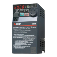
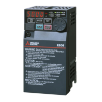
Do you have a question about the Mitsubishi Electric FR-E840-0040 and is the answer not in the manual?
Guidelines for installing the inverter in its environment and designing enclosures.
Illustrates wiring diagrams for standard, Ethernet, and safety communication models.
Describes the main circuit terminals and their functions for power and motor connections.
Details control circuit terminals, signals, and their functions.
Discusses EMI, leakage currents, and necessary countermeasures.
A comprehensive checklist to ensure correct installation and preparation before initial operation.
Explains how to implement failsafe systems using inverter status output signals.
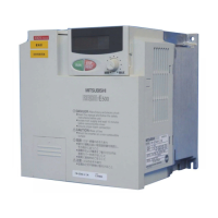
| Model | FR-E840-0040 |
|---|---|
| Series | FR-E800 |
| Category | Inverter |
| Manufacturer | Mitsubishi Electric |
| Frequency Range | 0.5 - 400 Hz |
| Protection Level | IP20 |
| Overload Capacity | 150% for 60 seconds |
| Enclosure Rating | IP20 |
| Control Method | V/f control, Vector control |
| Protective Structure | Open type |
| Protection Features | Overcurrent, Overvoltage, Undervoltage, Overload |
| Communication Options | CC-Link, Ethernet |
| Cooling Method | Fan cooling |
| Operating Temperature | -10°C to +50°C |
| Storage Temperature | -20°C to +65°C |
| Ambient Humidity | 95% RH or less (non-condensing) |
| Vibration Resistance | 5.9 m/s² |





 Loading...