EasyManua.ls Logo

Mitsubishi Electric FR-E800 Series User Manual

Mitsubishi Electric FR-E800 Series
484 pages
To Next Page IconTo Next Page
Page #1 background imageLoading...
Page #1 background image
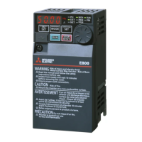
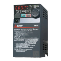
INVERTER
INVERTER FR-E800 Instruction Manual (Function)
C
HEAD OFFICE: TOKYO BUILDING 2-7-3, MARUNOUCHI, CHIYODA-KU, TOKYO 100-8310, JAPAN
IB(NA)-0600868ENG-C(2006)MEE Printed in Japan Specifications subject to change without notice.
FR-E800
Instruction Manual (Function)
FR-E820-0008(0.1K) to 0330(7.5K)
FR-E840-0016(0.4K) to 0170(7.5K)
FR-E860-0017(0.75K) to 0120(7.5K)
FR-E820S-0008(0.1K) to 0110(2.2K)
FR-E820-0008(0.1K) to 0330(7.5K)E
FR-E840-0016(0.4K) to 0170(7.5K)E
FR-E860-0017(0.75K) to 0120(7.5K)E
FR-E820S-0008(0.1K) to 0110(2.2K)E
FR-E820-0008(0.1K) to 0330(7.5K)SCE
FR-E840-0016(0.4K) to 0170(7.5K)SCE
FR-E860-0017(0.75K) to 0120(7.5K)SCE
FR-E820S-0008(0.1K) to 0110(2.2K)SCE
Compact, high functionality inverters
Model
FR-E800 Instruction
Manual (Function)
Model code 1A2-P91
COVER_E800_Function.fm 1 ペー 2020年6月24日 水曜日 午後3時27分

Table of Contents

Questions and Answers:

Mitsubishi Electric FR-E800 Series Specifications

General IconGeneral
BrandMitsubishi Electric
ModelFR-E800 Series
CategoryInverter
LanguageEnglish

Summary

CHAPTER 1 Introduction

1.1 Inverter model

Check the rating plate on the side of the product to identify specification details like voltage class, phases, capacity, communication type, and origin.

CHAPTER 2 Basic Operation

2.1 Operation panel

Details the components of the operation panel for standard, Ethernet, and safety communication models, explaining key functions and indicators.

2.8 I/O terminal function assignment

Details how to assign functions to external I/O terminals and communication terminals by setting parameters.

CHAPTER 3 Parameters

3.2 Parameter list (by parameter number)

Provides a comprehensive list of all parameters, organized by parameter number, with their settings, initial values, and refer pages.

CHAPTER 4 Control Method

4.1 Vector control and Real sensorless vector control

Explains vector control techniques for induction motors, including the equivalent circuit and current classification.

4.2 Changing the control method and mode

Guides on selecting control methods (V/F, Vector, Sensorless, PM) and modes (speed, torque) using parameter settings.

4.4 Selecting the PM sensorless vector control

Explains the process of initializing parameters for PM sensorless vector control, including offline auto tuning.

CHAPTER 5 Speed Control

5.1 Setting procedure of Real sensorless vector control (speed control)

Provides a step-by-step guide for setting up Real sensorless vector control for speed control, including parameter configuration and auto tuning.

5.2 Setting procedure of Vector control (speed control)

Details the procedure for setting up Vector control for speed control, covering wiring, motor specifications, and auto tuning.

5.3 Setting procedure of PM sensorless vector control (speed control)

Explains how to set up PM sensorless vector control for speed control, including parameter configuration and auto tuning.

5.4 Setting the torque limit level

Guides on setting the torque limit level to prevent overspeeding and describes methods for selecting torque limit input.

5.5 Performing high-accuracy, fast-response control (gain adjustment for Real sensorless vector control, Vector control, and PM sensorless vector control)

Explains how to adjust gain parameters for Real sensorless vector, Vector, and PM sensorless vector controls to improve performance and reduce vibration.

CHAPTER 6 Torque Control

6.1 Torque control

Explains torque control under Real sensorless vector control or Vector control, covering output torque, motor speed, and overspeed prevention.

6.2 Setting procedure of Real sensorless vector control (torque control)

Provides a step-by-step guide for setting up Real sensorless vector control for torque control, including parameter configuration and auto tuning.

6.3 Setting procedure for Vector control (torque control)

Details the procedure for setting up Vector control for torque control, covering wiring, motor specifications, and auto tuning.

6.4 Torque command

Explains how to select the torque command source, including analog input, parameter settings, and communication methods.

6.5 Speed limit

Guides on setting the speed limit value to prevent overspeeding and describes how control methods switch when the speed limit is reached.

CHAPTER 7 Adjustment during Real sensorless vector control, Vector control, PM sensorless vector control

7.3 Gain adjustment of current controllers for the d axis and the q axis

Details how to adjust the proportional gain and integral time of current controllers for the d and q axes to improve control performance.

CHAPTER 8 (E) Environment Setting Parameters

8.10 Parameter write selection

Details how to enable or disable parameter writing to prevent rewriting by misoperation.

8.16 Inverter parts life display

Details how to diagnose the deterioration of control circuit capacitor, main circuit capacitor, cooling fan, and inrush current limit circuit.

CHAPTER 9 (F) Settings for Acceleration/Deceleration

9.1 Setting the acceleration and deceleration time

Explains how to set motor acceleration/deceleration time using parameters, allowing for slower or faster adjustments.

9.6 Shortest acceleration/deceleration (automatic acceleration/deceleration)

Describes how to set parameters for shortest acceleration/deceleration, useful when motor constants are unknown or for machines needing quick response.

CHAPTER 10 (D) Operation Command and Frequency Command

10.1 Operation mode selection

Guides on selecting the inverter's operation mode (PU, External, Network, Combined) using parameters or communication.

10.3 Start command source and frequency command source during communication operation

Details selecting command sources for operation and frequency via communication, external terminals, or the PU.

CHAPTER 11 (H) Protective Function Parameters

11.1 Motor overheat protection (electronic thermal O/L relay)

Details setting current parameters to protect the motor from overheating, considering low cooling capability during low-speed operation.

11.7 Retry function

Explains the function that allows the inverter to reset itself and restart automatically after a fault indication.

11.8 Limiting the output frequency (maximum/minimum frequency)

Guides on setting upper and lower limits for the output frequency to prevent motor overspeeding or ensure minimum speed.

11.10 Stall prevention operation

Explains the function that monitors output current and automatically adjusts output frequency to prevent inverter shutoff due to overcurrent or overvoltage.

11.11 Load characteristics fault detection

Covers monitoring load conditions by storing speed/torque relationships to detect mechanical faults or for maintenance.

11.12 Motor overspeeding detection

Details the function that activates when motor speed exceeds the overspeed detection level to prevent accidental speeding.

CHAPTER 12 (M) Item and Output Signal for Monitoring

12.2 Monitor item selection on operation panel or via communication

Covers selecting monitor items to be displayed on the operation panel or via communication.

12.6 Output terminal function selection

Describes how to change functions of open collector output terminals and relay output terminals.

CHAPTER 13 (T) Multi-Function Input Terminal Parameters

13.6 Input terminal function selection

Guides on selecting or changing input terminal functions and checking available terminals for each parameter.

CHAPTER 14 (C) Motor Constant Parameters

14.1 Applied motor

Explains how to set the applied motor type to select appropriate thermal characteristics and motor constants.

14.2 Offline auto tuning

Details the process of offline auto tuning for optimal motor operation, including setting motor parameters and performing tuning.

14.3 Offline auto tuning for a PM motor (motor constant tuning)

Explains offline auto tuning specifically for PM motors to measure and set motor constants for optimal performance.

CHAPTER 15 (A) Application Parameters

15.1 Brake sequence function

Explains how to output operation timing signals for mechanical brakes, useful for preventing load slippage and overcurrent alarms.

15.4 PID control

Details performing process control for flow rate, air volume, or pressure using PID control with feedback from analog signals or parameters.

CHAPTER 16 (G) Control Parameters

CHAPTER 17 Checking and Clearing of Settings

17.1 Parameter clear / All parameter clear

Explains how to initialize parameters to their factory default values or clear all settings.

CHAPTER 18 Appendix

18.4 Parameters (functions) and instruction codes under different control methods

Lists parameters, functions, and instruction codes and their availability across different control methods (V/F, Vector, Sensorless, PM).

Related product manuals