EasyManua.ls Logo

Mitsubishi Electric FR-E840-0170E User Manual

Mitsubishi Electric FR-E840-0170E
484 pages
To Next Page IconTo Next Page
Page #1 background imageLoading...
Page #1 background image
INVERTER
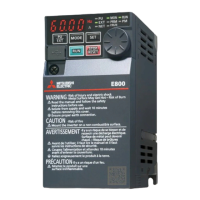
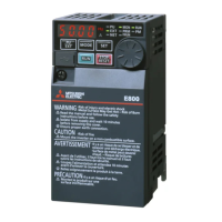
INVERTER FR-E800 Instruction Manual (Function)
C
HEAD OFFICE: TOKYO BUILDING 2-7-3, MARUNOUCHI, CHIYODA-KU, TOKYO 100-8310, JAPAN
IB(NA)-0600868ENG-C(2006)MEE Printed in Japan Specifications subject to change without notice.
FR-E800
Instruction Manual (Function)
FR-E820-0008(0.1K) to 0330(7.5K)
FR-E840-0016(0.4K) to 0170(7.5K)
FR-E860-0017(0.75K) to 0120(7.5K)
FR-E820S-0008(0.1K) to 0110(2.2K)
FR-E820-0008(0.1K) to 0330(7.5K)E
FR-E840-0016(0.4K) to 0170(7.5K)E
FR-E860-0017(0.75K) to 0120(7.5K)E
FR-E820S-0008(0.1K) to 0110(2.2K)E
FR-E820-0008(0.1K) to 0330(7.5K)SCE
FR-E840-0016(0.4K) to 0170(7.5K)SCE
FR-E860-0017(0.75K) to 0120(7.5K)SCE
FR-E820S-0008(0.1K) to 0110(2.2K)SCE
Compact, high functionality inverters
Model
FR-E800 Instruction
Manual (Function)
Model code 1A2-P91
COVER_E800_Function.fm 1 ペー 2020年6月24日 水曜日 午後3時27分

Table of Contents

Questions and Answers:

Mitsubishi Electric FR-E840-0170E Specifications

General IconGeneral
BrandMitsubishi Electric
ModelFR-E840-0170E
CategoryInverter
LanguageEnglish

Summary

Chapter 1 Introduction

1.2 Operation steps

Provides a flowchart and explanation of the basic operation steps for installing, setting up, and operating the inverter.

Chapter 2 Basic Operation

2.1 Operation panel

Details the components of the standard and Ethernet/safety communication model operation panels, including indicators and keys.

Chapter 3 Parameters

3.2 Parameter list (by parameter number)

Provides a comprehensive list of inverter parameters, including their function, setting range, and refer to page.

Chapter 4 Control Method

4.1 Vector control and Real sensorless vector control

Explains the fundamental equivalent circuit of an induction motor and the principles of Vector and Real sensorless vector control.

4.2 Changing the control method and mode

Details how to set the control method (V/F, Advanced magnetic flux vector, Real sensorless vector, Vector, PM sensorless vector) and control mode.

Chapter 5 Speed Control

5.1 Setting procedure of Real sensorless vector control (speed control)

Provides detailed steps for setting up Real sensorless vector control for speed control operations.

5.2 Setting procedure of Vector control (speed control)

Outlines the procedure for setting up Vector control for speed control, including wiring and parameter settings.

5.3 Setting procedure of PM sensorless vector control (speed control)

Explains the steps for setting up PM sensorless vector control for speed control, including motor parameter initialization.

5.4 Setting the torque limit level

Details how to limit the output torque to prevent overspeeding, covering parameter selection and analog input methods.

5.5 Performing high-accuracy, fast-response control (gain adjustment for Real sensorless vector control, Vector control, and PM sensorless vector control)

Guides on adjusting speed control gain for optimal performance, addressing vibration, noise, slow response, and overshoot.

5.8 Avoiding motor overrunning

Provides methods to avoid motor overrunning due to excessive load torque or incorrect encoder pulse settings.

5.9 Troubleshooting in the speed control

Offers solutions for common speed control issues like motor not rotating, incorrect speed, hunting, and acceleration/deceleration problems.

Chapter 6 Torque Control

6.1 Torque control

Explains torque control under Real sensorless vector control or Vector control, focusing on outputting commanded torque.

6.2 Setting procedure of Real sensorless vector control (torque control)

Provides detailed steps for setting up Real sensorless vector control for torque control operations.

6.3 Setting procedure for Vector control (torque control)

Details the procedure for setting up Vector control for torque control, including wiring and parameter configuration.

6.4 Torque command

Explains how to select the torque command source, covering analog input, parameter settings, and communication.

6.5 Speed limit

Describes how to set the speed limit value to prevent motor overspeeding during torque control.

6.6 Torque control gain adjustment

Guides on adjusting torque control gain to improve performance and address issues like vibration or overcurrent.

6.7 Troubleshooting in torque control

Provides solutions for common issues encountered during torque control operation, such as incorrect operation or torque variation.

Chapter 9 (F) Settings for Acceleration/Deceleration

9.1 Setting the acceleration and deceleration time

Explains how to set motor acceleration/deceleration time and multiple acceleration/deceleration times using parameters.

Chapter 10 (D) Operation Command and Frequency Command

10.1 Operation mode selection

Explains how to select the inverter operation mode (PU, External, Network, Combined) using parameters or signals.

10.3 Start command source and frequency command source during communication operation

Explains how to select command sources for operation and frequency via communication, external terminals, or PU.

CHAPTER 11 (H) Protective Function Parameters

11.1 Motor overheat protection (electronic thermal O/L relay)

Explains how to set current for electronic thermal relay to protect the motor from overheating and match temperature characteristics.

11.7 Retry function

Explains how the inverter can reset itself and restart at protective function activation, with selectable retry generating faults.

11.8 Limiting the output frequency (maximum/minimum frequency)

Describes how to clamp the upper and lower limits of the output frequency to prevent motor overspeeding.

11.10 Stall prevention operation

Describes how the inverter automatically changes output frequency to prevent shutoff due to overcurrent or overvoltage.

11.11 Load characteristics fault detection

Explains how to monitor load operating conditions and activate protective functions or output warnings when deviations occur.

11.12 Motor overspeeding detection

Details how Overspeed occurrence (E.OS) is activated when motor speed exceeds the detection level, preventing accidental speeding.

CHAPTER 12 (M) Item and Output Signal for Monitoring

12.2 Monitor item selection on operation panel or via communication

Describes how to select monitor items displayed on the operation panel or via communication.

CHAPTER 13 (T) Multi-Function Input Terminal Parameters

13.1 Analog input selection

Describes how to select analog input terminal specifications and forward/reverse rotation by input signal polarity.

13.4 Frequency setting voltage (current) bias and gain

Explains how to set magnitude (slope) of output frequency in relation to torque setting signal and adjust bias/gain.

13.5 Torque (magnetic flux) setting current (voltage) bias and gain

Describes how to set magnitude (slope) of torque in relation to torque setting signal and adjust bias/gain.

13.6 Input terminal function selection

Explains how to select or change input terminal functions and check terminal availability for each parameter.

13.7 Inverter output shutoff

Describes how to shut off the inverter output with the MRS signal and select the logic of the MRS signal.

13.9 Start signal operation selection

Describes how to select the start signal (STF/STR) operation and stopping method (deceleration or coasting) at turn-OFF.

CHAPTER 14 (C) Motor Constant Parameters

14.1 Applied motor

Explains how to select the motor type and set parameters for optimal operation and electronic thermal O/L relay function.

14.2 Offline auto tuning

Guides on performing offline auto tuning to enable optimal operation, especially for PM motors and when using non-Mitsubishi motors.

14.3 Offline auto tuning for a PM motor (motor constant tuning)

Details the procedure for offline auto tuning specifically for PM motors to measure and set motor constants.

CHAPTER 15 (A) Application Parameters

15.4 PID control

Details how to perform process control (flow, air volume, pressure) using feedback systems and PID control.

CHAPTER 16 (G) Control Parameters

16.6 DC injection brake, zero speed control, servo lock, and magnetic flux decay output shutoff

Details how to adjust braking torque and timing, and select zero speed control, servo lock, and magnetic flux decay.

CHAPTER 18 Appendix

18.4 Parameters (functions) and instruction codes under different control methods

Provides a comprehensive table showing parameter availability across different control methods (V/F, Vector, Sensorless, PM).

Related product manuals