Installation and wiring Installation of the inverter and enclosure design
FR-F800 2 - 23
2.3.4 Panel through attachment procedure
When encasing the inverter to an enclosure, the heat generated in the enclosure can be greatly re-
duced by protruding the heatsink of the inverter.
When installing the inverter in a compact enclosure, etc., this installation method is recommended.
When using a panel through attachment (FR-A8CN)
For the FR-F820-00105(2.2K) to 04750(110K) and the FR-F840-00023(0.75K) to 03610(160K), a heat-
sink can be protruded outside the enclosure using a panel through attachment (FR-A8CN). (For the
FR-F840-04320(185K) or higher, attachment is not necessary when the heatsink is to be protruded.)
For a panel cut dimension drawing and an installation procedure of the panel through attachment
(FR-A8CN) to the inverter, refer to a manual of FR-A8CN.
Protrusion of heatsink of the FR-F840-04320(185K) or higher
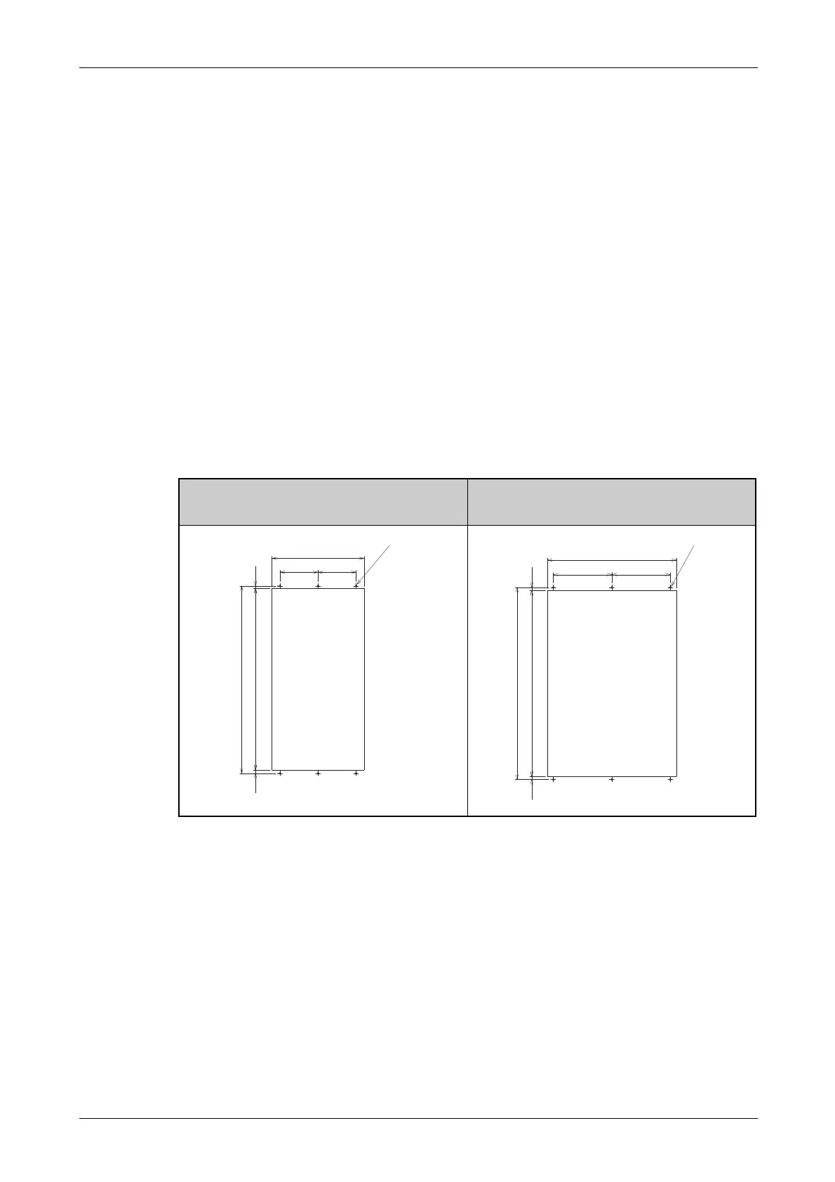
● Panel cutting
Cut the panel of the enclosure according to the inverter capacity.
FR-F840-04320(185K),
FR-F840-04810(220K)
FR-F840-05470(250K)
FR-F840-06100(280K)
FR-F840-06830(315K)
I002800E I002801E
Tab. 2-8: Dimensions of the cut-out for the heatsink protrusion
 Loading...