1/2
JY997D49401H
Safety Precautions
(Read these precautions before use.)
If the equipment is used in a manner not specified by the manufacturer, the
protection provided by the equipment may be impaired.
This manual classifies the safety precautions into two categories:
and .
Depending on the circumstances, procedures indicated by may also
cause severe injury.
It is important to follow all precautions for personal safety.
Indicates that incorrect handling may cause hazardous
conditions, resulting in death or severe injury.
Indicates that incorrect handling may cause hazardous
conditions, resulting in medium or slight personal injury
or physical damage.
STARTUP AND
MAINTENANCE
PRECAUTIONS
• Do not touch any terminal while the PLC's power is on.
Doing so may cause electric shock or malfunctions.
• Before cleaning or retightening terminals, cut off all phases of the power
supply externally.
Failure to do so may cause electric shock.
• This product shall be powered by a UL Listed or Recognized 24 V DC
isolating source when the DC power supply type product is powered by a
power supply converted from hazardous voltages.
• Use the battery for memory backup correctly in conformance to FX
3G Series
User's Manual - Hardware Edition.
- Use the battery only for the specified purpose.
- Connect the battery correctly.
- Do not charge, disassemble, heat, put in fire, short-circuit, connect
reversely, weld, swallow or burn the battery, or apply excessive forces
(vibration, impact, drop, etc.) to the battery.
- Do not store or use the battery at high temperatures or expose to direct
sunlight.
Overview
FX3GE PLC has an Ethernet communication function and analog input/output function
built into a base that is FX
3G PLC.
The Ethernet communication function is equivalent to FX
3U-ENET-ADP.
The analog input/output function (analog input 2 channels, analog output 1 channel) is
equivalent to FX
3U-3A-ADP.
Associated manuals
STARTUP AND
MAINTENANCE
PRECAUTIONS
- Do not expose to water, bring near fire or touch liquid leakage or other contents
directly.
- When replacing the battery, make sure to use our specified product (FX
3U-
32BL).
- When a battery error occurs ("ALM" LED is lit in red), follow the description in
FX
3G Series User's Manual - Hardware Edition.
- Incorrect handling of the battery may cause heat excessive generation,
bursting, ignition, liquid leakage or deformation, and lead to injury, fire or
failures and malfunctions of facilities and other equipment.
• Before modifying or disrupting the program in operation or running the PLC,
carefully read through this manual and the associated manuals and ensure the
safety of the operation.
An operation error may damage the machinery or cause accidents.
STARTUP AND
MAINTENANCE
PRECAUTIONS
• Turn off the power to the PLC before attaching or detaching the memory cassette.
If the memory cassette is attached or detached while the PLC's power is on, the
data in the memory may be destroyed, or the memory cassette may be damaged.
• Do not disassemble or modify the PLC.
Doing so may cause fire, equipment failures, or malfunctions.
For repair, contact your local Mitsubishi Electric representative.
• Turn off the power to the PLC before connecting or disconnecting any extension
cable.
Failure to do so may cause equipment failures or malfunctions.
• Turn off the power to the PLC before attaching or detaching the following devices.
Failure to do so may cause equipment failures or malfunctions.
- Peripheral devices, display module, and expansion boards
- Extension units/blocks and special adapters
- Battery and memory cassette
• For cleaning, perform dry wiping without using chemicals.
• If there is the possibility of touching the PLC inside a control panel in
maintenance,make sure to discharge to avoid the influence of static electricity.
DISPOSAL PRECAUTIONS
• Please contact a certified electronic waste disposal company for the
environmentally safe recycling and disposal of your device.
When disposing of batteries, separate them from other waste according to local
regulations.
(For details of the Battery Directive in EU countries, refer to FX
3G Series User's
Manual - Hardware Edition.)
TRANSPORTATION AND
STORAGE PRECAUTIONS
• When transporting the FX3GE Series PLC incorporating the optional battery, turn
on the PLC before shipment, confirm that the battery mode is set using a
parameter and the ALM LED is OFF, and check the battery life.
If the PLC is transported with the ALM LED on or the battery exhausted, the
battery-backed data may be unstable during transportation.
• The PLC is a precision instrument. During transportation, avoid impacts larger
than those specified in Section 3.1. Failure to do so may cause failures in the
PLC.
After transportation, verify the operations of the PLC.
• When transporting lithium batteries, follow required transportation regulations.
(For details of the regulated products, refer to FX
3G Series User's Manual -
Hardware Edition.)
How to obtain manuals
For the necessary product manuals or documents, consult with your local Mitsubishi
Electric representative.
Associated manuals
FX
3GE Series PLC (main unit) comes with this document (hardware manual).
For a detailed explanation of the FX
3GE
Series hardware and information on instructions
for PLC programming and special function unit/block, refer to the relevant documents.
Specifications not described in this manual are same as FX3G PLC. For details, refer to
the following manual.
→ Refer to FX
3G Series User's Manual - Hardware Edition.
Certification of UL, cUL standards
Please consult with Mitsubishi Electric for information on UL, cUL standard practices
and the corresponding types of equipment.
Compliance with EC directive (CE Marking)
This product complies with EC directive, however, this document does not guarantee
that a mechanical system including this product will comply with the following
standards.
Compliance to EMC directive and LVD directive of the entire mechanical system should
be checked by the user/manufacturer. For more details please contact the local
Mitsubishi Electric sales site.
Requirement for Compliance with EMC directive
The following products have shown compliance through direct testing (of the identified
standards below) and design analysis (through the creation of a technical construction
file) to the European Directive for Electromagnetic Compatibility (2014/30/EU) when
used as directed by the appropriate documentation.
Attention
This product is designed for use in industrial applications.
Type : Programmable Controller (Open Type Equipment)
Models : MELSEC FX
3GE series manufactured
from March 1st, 2013 FX
3GE-MR/ES
from June 1st, 2013 FX
3GE-MT/ES FX3GE-MT/ESS
from August 1st, 2013 FX
3GE-MR/DS FX3GE-MT/DS
FX
3GE-MT/DSS
Where indicates: 24, 40
Manual name Manual No. Description
FX
3G Series User's Manual
- Hardware Edition
JY997D31301
MODEL CODE:
09R521
Explains FX
3G Series PLC
specification details for I/O,
wiring, installation, and
maintenance.
FX
3S
/FX
3G
/FX
3GC
/FX
3U
/
FX
3UC
Series
Programming Manual
- Basic & Applied Instruction
Edition
JY997D16601
MODEL CODE:
09R517
Describes PLC programming for
basic/applied instructions STL/
SFC programming and devices.
MELSEC-Q/L/F Structured
Programming Manual
(Fundamentals)
SH-080782
MODEL CODE:
13JW06
Programming methods,
specifications, functions, etc.
required to create structured
programs.
FXCPU Structured
Programming Manual
[Device & Common]
JY997D26001
MODEL CODE:
09R925
Devices, parameters, etc.
provided in structured projects of
GX Works2.
FXCPU Structured
Programming Manual
[Basic & Applied Instruction]
JY997D34701
MODEL CODE:
09R926
Sequence instructions provided
in structured projects of GX
Works2.
FXCPU Structured
Programming Manual
[Application Functions]
JY997D34801
MODEL CODE:
09R927
Application functions provided in
structured projects of GX Works2.
FX Series User’s Manual
- Data Communication Edition
JY997D16901
MODEL CODE:
09R715
Explains N:N link, parallel link,
computer link, no protocol
communication by RS
instructions/FX
2N-232IF.
FX
3S
/FX
3G
/FX
3GC
/FX
3U
/
FX
3UC
Series User's Manual
- Analog Control Edition
JY997D16701
MODEL CODE:
09R619
Describes specifications for
analog control and programming
methods for FX
3S/FX3G/FX3GC/
FX
3U/FX3UC Series PLC.
FX
3S
/FX
3G
/FX
3GC
/FX
3U
/
FX
3UC
Series User's Manual
- Positioning Control Edition
JY997D16801
MODEL CODE:
09R620
Explains the specifications for
positioning control of
FX
3S
/FX
3G
/
FX
3GC
/FX
3U
/FX
3UC
Series and
programming
procedures
FX
3U-ENET-ADP
User's Manual
JY997D45801
MODEL CODE:
09R725
Describes FX
3U-ENET-ADP
Ethernet communication special
adapter details.
Requirement for Compliance with LVD directive
The following products have shown compliance through direct testing (of the
identified standards below) and design analysis (through the creation of a
technical construction file) to the European Directive for Low Voltage (2014/35/
EU) when used as directed by the appropriate documentation.
Type : Programmable Controller (Open Type Equipment)
Models : MELSEC FX
3GE series manufactured
from March 1st, 2013 FX
3GE-MR/ES
from June 1st, 2013 FX
3GE-MT/ES FX3GE-MT/ESS
from August 1st, 2013 FX
3GE-MR/DS
Where indicates: 24, 40
For the products above,PLCs manufactured
before February 28th, 2018 are compliant with EN61131-2:2007,
PLCs manufactured after March 1st, 2018 are compliant with EN61010-2-
201:2013.
*1
*1 For some models, PLCs manufactured after January 1st, 2018 are
compliant.
Caution for compliance with EC Directive
• Please use the FX3GE Series programmable controllers while installed in
conductive shielded control boxes.
• Please secure the control box lid to the control box (for conduction).
Installation within a control box greatly affects the safety of the system and aids
in shielding noise from the programmable controller.
• For the control panel, use the product having sufficient strength, fire
protectiveness and shielding property to an installation environment.
Caution for compliance with the LVD directive (EN61010-2-201:2013)
*2
• To an external connection port other than AC power supply terminal and AC
input/output terminal, connect the circuit separated from a dangerous voltage
by a double/reinforced insulation.
• Between the commons having the adjacent relay output terminals, if an
external power supply is higher than 120 V AC, the insulation is basic.
Therefore, when using 120 V AC or higher external power supply and 30 V DC/
AC or lower external power supply between the adjacent commons, do not
handle 30 V DC/AC or lower external power supply as a touchable part, (When
handling 30 V DC/AC or lower external power supply as a touchable part, add
a basic insulation.)
• Do not wire two or more crimp terminals to one terminal. (If the wiring with two
or more wires is needed,take an appropriate action such as adding an external
terminal.)
• For crimp terminals to be used for the wiring applied with 30 V AC or higher,
use the products with insulating sleeves.
• Cutoff device such as a breaker or a circuit protector should be installed in
accordance with the following precautions.
- Use EN60947-1 or EN60947-3 standards.
- Place the cutoff device so that it can be operated easily.
- Specify that the cutoff device is for this equipment.
*2 For the time of compliance with the LVD directive (EN61010-2-201:2013),
refer to FX3G Series User's Manual - Hardware Edition.
Standard Remark
EN61131-2:2007
Programmable controllers
- Equipment requirements and
tests
Compliance with all relevant aspects of
the standard.
EMI
• Radiated Emission
• Conducted Emission
EMS
• Radiated electromagnetic field
• Fast transient burst
• Electrostatic discharge
• High-energy surge
• Voltage drops and interruptions
• Conducted RF
• Power frequency magnetic field
Standard Remark
EN61131-2:2007
Programmable controllers
- Equipment requirements and tests
The equipment has been assessed
as a component for fitting in a
suitable control box which meets the
requirements of EN61131-2:2007
EN61010-2-201:2013
Safety of electrical equipment for
measurement,control,and test
The equipment has been assessed
as a component for fitting in a
suitable control box which meets the
requirements of EN61010-2-
201:2013
Analog input/output
The analog input/output have been found to be compliant to the European
standards in the aforesaid manual and directive. However, for the very best
performance from what are in fact delicate measuring and controlled output
devices, Mitsubishi Electric would like to make the following points.
As analog devices are sensitive by nature, their use should be considered
carefully. For users of proprietary cables (integral with sensors or actuators),
these users should follow those manufacturers' installation requirements.
Mitsubishi Electric recommends that shielded cables be used. If NO other EMC
protection is provided, users may experience temporary loss or accuracy between
+10% / -10% in very heavy industrial areas.
However, Mitsubishi Electric suggests that adequate EMC precautions be
followed for the users complete control system.
- Sensitive analog cables should not be laid in the same trunking or cable
conduit as high voltage cabling. Where possible, users should run analog
cables separately.
- Good cable shielding should be used. When terminating the shield at Earth,
ensure that no earth loops are accidentally created.
- When reading analog values, EMC accuracy can be improved by averaging
the readings. This can be achieved either through functions on the analog
products or through a user's program in the FX
3GE Series PLC main unit.
Incorporated Items
Check if the following product and items are included in the package.
1. Features and cautions on using FX3GE PLC
FX3GE PLC has an Ethernet communication function and analog input/output
function built into a base that is FX
3G PLC.
This section describes below differences between FX
3G and FX3GE and cautions
on use.
For details, refer also to the FX
3G Series User's Manual - Hardware Edition.
→ Refer to FX
3G Series User's Manual - Hardware Edition.
1.1 Additional function from the FX3G series
• Ethernet communication function
The PLC has a Ethernet communication function (Equivalent to FX
3U-ENET-
ADP).
• Analog input/output function
The PLC has analog input 2 channels, analog output 1 channel (Equivalent to
FX3U-3A-ADP). Specifications differ from FX3U-3A-ADP in part. For details,
refer to Chapter 6.
1.2 Programming tool
GX Works2 Ver. 1.91V or later can be used. Select "FX3G" in "PLC Type". When
setting "Ethernet port settings", using GX Works2 Ver.1.91V or later.
FX-30P and GX Developer can also be used. However, "Ethernet port setting"
cannot be set.
In the case that the version does not support FX
3G, the programming tool can still
be used by choosing FX
1N. However, programming is enabled only in the
functional range such as instructions, device ranges and program sizes available
in a PLC selected as the alternative model.
1.3 Using the built-in Ethernet
When GX Works2 or MX Component is used, set the parameter settings and
connection destination settings of the built-in Ethernet using the same settings as
FX
3U-ENET-ADP.
1.4 Terminal block
The input/output terminal block of FX3GE series PLC is built-in.
Terminal block cannot be removed.
Included Items
Main units
FX
3GE-24M,
FX
3GE-40M
Product 1 unit
Dust proof protection sheet 1 sheet
Manuals [English] 1 manual
1.5 System configuration
- Special adapters can be directly connected to the main unit.
(It is not necessary to connect a connector conversion adapter.)
- One communication and one analog expansion option can be connected.
Expansion is available for one expansion board and two special adapters. But the
expansion board cannot be connected when two special adapters are connected.
- 40 point I/O type cannot use the BD1 slot.
-FX
3G-CNV-ADP, FX3U-ENET-ADP cannot be connected.
- The communication channel of the built-in Ethernet is CH1. When a
communication expansion board or a communication special adapter is
connected to the PLC, that communication channel becomes CH2.
- The built-in analog is the analog special adapter first unit.
When an analog expansion board is connected, the analog expansion board
becomes second unit. When an analog special adapter is connected, the analog
special adapter becomes second unit.
Please refer to the following for details.
1) In the case of 40 point type
Analog
special adapter
Communication
special adapter
BD2
slot
FX
3U
-232ADP (-MB)
FX
3U
-485ADP (-MB)
[Communication]
FX
3G
-232-BD
FX
3G
-485-BD
FX
3G
-485-BD-RJ
FX
3G
-422-BD
[Input]
FX
3G
-4EX-BD
[Output]
FX
3G
-2EYT-BD
[Analog volume]
FX
3G
-8AV-BD
One unit
FX
3U
-4AD-ADP
FX
3U
-4DA-ADP
FX
3U
-3A-ADP
[Analog input/output]
FX
3G
-2AD-BD
FX
3G
-1DA-BD
One unit
Maximum one unit
Cannot use
BD1 slot
Expansion board
Maximum one unit
FX
3U
-4AD-PT-ADP
FX
3U
-4AD-PTW-ADP
FX
3U
-4AD-PNK-ADP
FX
3U
-4AD-TC-ADP
FX
3G
-EEPROM-32L
FX
3G
-5DM
(Can be connected on top of other boards.)
2) In the case of 24 point type
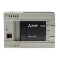
2. Outline
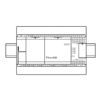
2.1 Part names
For the input/output extension units/blocks, refer to the following manual.
→ Refer to FX
3G Series User's Manual - Hardware Edition.
No. Name
[1] Peripheral device connector cover
[2] Terminal names
[3] Top cover (S) (40points type only)
[4] Top cover
[5] Terminal block covers
[6] Input display LEDs (red)
[7] Extension device connector cover
[8]
Operation status display LEDs
POW Green On while power is on the PLC.
RUN Green On while the PLC is running.
ERR
Red Flashing when a program error occurs.
Red Lit when a CPU error occurs.
ALM Red
Lit when the battery voltage drops.
(When the optional battery is used)
[9] Output display LEDs (red)
[10] Model name (abbreviation)
Analog
special adapter
Communication
special adapter
BD2
slot
FX
3U-232ADP (-MB)
FX
3U-485ADP (-MB)
One unit
FX3U-4AD-ADP
FX
3U-4DA-ADP
FX
3U-3A-ADP
[Analog input/output]
FX3G-2AD-BD
FX
3G-1DA-BD
One unit
Maximum one unit
Maximum one unit
FX3U-4AD-PT-ADP
FX
3U-4AD-PTW-ADP
FX
3U-4AD-PNK-ADP
FX
3U-4AD-TC-ADP
FX
3G-EEPROM-32L
FX
3G-5DM
(Can be connected on top of other boards.)
Expansion board
[Communication]
FX3G-232-BD
FX
3G-485-BD
FX
3G-485-BD-RJ
FX
3G-422-BD
[Input]
FX3G-4EX-BD
[Output]
FX3G-2EYT-BD
[Analog volume]
FX3G-8AV-BD
[1][12] [2] [3] [4] [5]
[10]
[11]
[5][13][14][16] [15]
[7]
[8]
[6]
[9]
With terminal cover open
The authentication label for authorized products is affixed to the right side of the
product to avoid to be forged.
Products that do not have the genuine product certification label or nameplate are
not covered by the warranty.
is a mark that instructs to use the cable with an appropriate temperature rating
(80°C or more) for wiring.
2.2 LED status
PLC part
No. Name
[11] DIN rail mounting hooks
[12] Analog input terminal block
[13] Analog output terminal block
[14] 10BASE-T/100BASE-TX connector (RJ45)
[15] Ethernet status LEDs
[16] Special adapter connector cover
No. Name
[1] Peripheral device connector (USB)
[2] Peripheral device connector (RS-422)
[3] RUN/STOP switch
[4]
Variable analog potentiometers
Upper side : VR1, Lower side : VR2
[5] Terminal cover
[6] Optional equipment connector
[7] Power supply terminal, Input (X) terminals
[8] Battery connector
[9] Battery holder
[10] Power supply terminal, Output (Y) terminals
[11] Optional equipment connecting screw holes
[12] Special adapter connector
LED
display
LED
color
Status Description
POW Green
ON Power is on
OFF Power is off
RUN Green
ON Running
OFF Stopped
ERR Red
ON When a CPU error occurs.
Flicker When a program error occurs.
OFF When a normal status.
ALM Red
ON
When the battery voltage drops.
(When the optional battery is installed.)
OFF
When the battery voltage normal status.
(When the optional battery is installed.)
[8]
[1]
[2] [3]
[12]
[4] [5][5] [6] [7]
[10][11]
[9]
[5]
Right side
Genuine product certification label
Nameplate
FX3GE Series
Programmable Controller
HARDWARE MANUAL
This manual describes the part names, dimensions, mounting, and specifications
of the product. Before use, read this manual and the manuals of all relevant
products fully to acquire proficiency in handling and operating the product. Make
sure to learn all the product information, safety information, and precautions.
Store this manual in a safe place so that it can be taken out and read whenever
necessary. Always forward it to the end user.
Registration
Ethernet is a trademark of Xerox Corporation.
Phillips is a registered trademark of Phillips Screw Company.
The company and product names described in this manual are registered
trademarks or the trademarks of their respective companies.
Effective December 2017
Specifications are subject to change without notice.
© 2013 Mitsubishi Electric Corporation
Manual Number JY997D49401
Revision H
Date December 2017