FX3G SERIES PROGRAMMABLE
CONTROLLERS
HARDWARE MANUAL
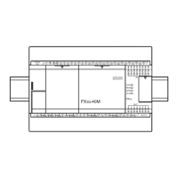
This manual describes the part names, dimensions, mounting,
cabling and specifications for the product. This manual is extracted
from FX
3G Series User's Manual - Hardware Edition. Refer to FX3G
Series User's Manual - Hardware Edition for more details. Before
use, read this manual and manuals of relevant products fully to
acquire proficiency in the handling and operating the product. Make
sure to learn all the product information, safety information, and
precautions.
And, store this manual in a safe place so that you can take it out and
read it whenever necessary. Always forward it to the end user.
Registration
Phillips is a registered trademark of Phillips Screw Company.
The company name and the product name to be described in this
manual are the registered trademarks or trademarks of each
company.
Effective December 2017
Specifications are subject to change without notice.
© 2011 Mitsubishi Electric Corporation
Safety Precaution (Read these precautions before use.)
If the equipment is used in a manner not specified by the
manufacturer, the protection provided by the equipment may be
impaired.
This manual classifies the safety precautions into two categories:
and .
Depending on the circumstances, procedures indicated by
may also cause severe injury.
It is important to follow all precautions for personal safety.
Manual Number JY997D46001
Revision F
Date December 2017
Indicates that incorrect handling may cause
hazardous conditions, resulting in death or
severe injury.
Indicates that incorrect handling may cause
hazardous conditions, resulting in medium or
slight personal injury or physical damage.
STARTUP AND
MAINTENANCE
PRECAUTIONS
• Do not touch any terminal while the PLC's power is on.
Doing so may cause electric shock or malfunctions.
• Before cleaning or retightening terminals externally cut off all
phases of the power supply.
Failure to do so may cause electric shock.
• Use the battery for memory backup correctly in FX
3G Series
User's Manual - Hardware Edition.
- Use the battery only for the specified purpose.
- Connect the battery correctly.
- Do not charge, disassemble, heat, put in fire, short-circuit,
connect reversely, weld, swallow or burn the battery, or apply
excessive forces (vibration, impact, drop, etc.) to the battery.
- Do not store or use the battery at high temperatures or
expose to direct sunlight.
- Do not expose to water, bring near fire or touch liquid
leakage or other contents directly.
- Incorrect handling of the battery may cause heat excessive
generation, bursting, ignition, liquid leakage or deformation,
and lead to injury, fire or failures and malfunctions of facilities
and other equipment.
- When replacing the battery, make sure to use our specified
product (FX
3U-32BL).
- When a battery error occurs ("ALM" LED is lit in red), follow
the description in FX
3G Series User's Manual - Hardware
Edition.
• Before modifying or disrupting the program in operation or
running the PLC, carefully read through this manual and the
associated manuals and ensure the safety of the operation.
An operation error may damage the machinery or cause accidents.
STARTUP AND
MAINTENANCE
PRECAUTIONS
• Turn off the power to the PLC before attaching or detaching the
memory cassette. If the memory cassette is attached or
detached while the PLC's power is on, the data in the memory
may be destroyed, or the memory cassette may be damaged.
• Do not disassemble or modify the PLC.
Doing so may cause fire, equipment failures, or malfunctions.
For repair, contact your local Mitsubishi Electric representative.
•
Turn off the power to the PLC before connecting or disconnecting
any extension cable.
Failure to do so may cause equipment failures or malfunctions.
• Turn off the power to the PLC before attaching or detaching the
following devices.
Failure to do so may cause equipment failures or malfunctions.
- Peripheral devices, Display module, expansion boards, and
special adapters
- Connector conversion adapter, extension blocks, and FX
Series terminal blocks
- Battery and memory cassette
• Do not use the chemicals for cleaning.
• If there is the possibility of touching the PLC inside a control
panel in maintenance, make sure to discharge to avoid the
influence of static electricity.
DISPOSAL
PRECAUTIONS
• Please contact a certified electronic waste disposal company
for the environmentally safe recycling and disposal of your
device. When disposing of batteries, separate them from other
waste according to local regulations.
(For details of the Battery Directive in EU countries, refer to
FX3G Series User's Manual - Hardware Edition.)
Associated manuals
Associated manuals
FX3G Series PLC (main unit) comes with this document (hardware
manual).
For a detailed explanation of the FX3G Series hardware and
information on instructions for PLC programming and special
extension unit/block, refer to the relevant documents.
Certification of UL, cUL standards
Please consult with Mitsubishi Electric for information on UL, cUL
standard practices and the corresponding types of equipment.
Compliance with EC directive(CE Marking )
This product complies with EC directive, however, this document
does not guarantee that a mechanical system including this product
will comply with EC directive.
Compliance to EMC directive and LVD directive of the entire
mechanical system should be checked by the user / manufacturer.
For more details please contact the local Mitsubishi Electric sales
site.
Caution for compliance with EC Directive
• Please use the FX3G Series programmable controllers while
installed in conductive shielded control panels under a general
industrial environment.
• Programmable controllers are open-type devices that must be
installed and used within conductive control panels. Please
secure the control box lid to the control box (for conduction).
Installation within a control box greatly affects the safety of the
system and aids in shielding noise from the programmable
controller.
• For the control panel, use the product having sufficient strength,
fire protectiveness and shielding property to an installation
environment.
• 24 V DC of the power supply must be supplied from the circuit
double/reinforced insulated from the main power supply (MAINS).
Caution for compliance with the LVD directive (EN61010-2-
201:2013)(
*
1)
• To an external connection port other than AC power supply
terminal and AC input/output terminal, connect the circuit
separated from a dangerous voltage by a double/reinforced
insulation.
• Between the commons having the adjacent relay output
terminals, if an external power supply is higher than 120 V AC,
the insulation is basic. Therefore, when using 120 V AC or higher
external power supply and 30 V DC/AC or lower external power
supply between the adjacent commons, do not handle 30 V DC/
AC or lower external power supply as a touchable part, (When
handling 30 V DC/AC or lower external power supply as a
touchable part, add a basic insulation.)
TRANSPORTATION
AND STORAGE
PRECAUTIONS
• When transporting the FX3G Series PLC incorporating the
optional battery, turn on the PLC before shipment, confirm that
the battery mode is set using a parameter and the ALM LED is
OFF, and check the battery life.
If the PLC is transported with the ALM LED on or the battery
exhausted, the battery-backed data may be unstable during
transportation.
• The PLC is a precision instrument. During transportation, avoid
impacts larger than those specified in Section 2.1 by using
dedicated packaging boxes and shock-absorbing palettes.
Failure to do so may cause failures in the PLC.
After transportation, verify operation of the PLC and check for
damage of the mounting part, etc.
• When transporting lithium batteries, follow required
transportation regulations.
(For details of the regulated products, refer to FX
3G Series
User's Manual - Hardware Edition.)
How to obtain manuals
For the necessary product manuals or documents,
consult with your local Mitsubishi Electric representative.
Manual name Manual No. Description
FX
3G Series
User's Manual
- Hardware Edition
JY997D31301
MODEL CODE:
09R521
Explains FX3G Series
PLC specification details
for I/O, wiring,
installation, and
maintenance.
FX3S/FX3G/FX3GC/
FX3U/FX3UC Series
Programming Manual
- Basic & Applied
Instruction Edition
JY997D16601
MODEL CODE:
09R517
Describes PLC
programming for basic/
applied instructions STL/
SFC programming and
devices.
MELSEC-Q/L/F
Structured
Programming
Manual
(Fundamentals)
SH-080782
MODEL CODE:
13JW06
Programming methods,
specifications, functions,
etc. required to create
structured programs.
FXCPU Structured
Programming
Manual
[Device & Common]
JY997D26001
MODEL CODE:
09R925
Devices, parameters,
etc.
provided in structured
projects of GX Works2.
FXCPU Structured
Programming
Manual
[Basic & Applied
Instruction]
JY997D34701
MODEL CODE:
09R926
Sequence instructions
provided in structured
projects of GX Works2.
FXCPU Structured
Programming
Manual
[Application
Functions]
JY997D34801
MODEL CODE:
09R927
Application functions
provided in structured
projects of GX Works2.
FX Series
User’s Manual
- Data
Communication
Edition
JY997D16901
MODEL CODE:
09R715
Explains N:N link,
parallel link, computer
link, no protocol
communication by RS
instructions/FX2N-232IF.
FX3S/FX3G/FX3GC/
FX
3U/FX3UC Series
User's Manual
- Analog Control
Edition
JY997D16701
MODEL CODE:
09R619
Describes specifications
for analog control and
programming methods
for FX3S/FX3G/FX3GC/
FX
3U/FX3UC Series
PLC.
FX
3S/FX3G/FX3GC/
FX3U/FX3UC Series
User's Manual
- Positioning Control
Edition
JY997D16801
MODEL CODE:
09R620
Explains the
specifications for
positioning control of
FX3S/FX3G/FX3GC/
FX3U/FX3UC Series and
programming procedures
Manual name Manual No. Description
Side
B
Side
A
Side
B
JAPANESE ENGLISH
JY997D46001F