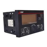
Do you have a question about the Mitsubishi Electric LE7-40GU and is the answer not in the manual?
| Brand | Mitsubishi Electric |
|---|---|
| Model | LE7-40GU |
| Category | Controller |
| Language | English |
Precautions related to product design and installation for safety.
Cut off power supply before installation/wiring to prevent electric shock or damage.
Ensure proper wiring to terminal blocks to prevent electric shock and equipment failure.
Do not disassemble or modify the product; turn off power before connecting/disconnecting cables.
Contact certified electronic waste disposal company for safe recycling and disposal.
General purpose part, not for human life systems. Consult Mitsubishi Electric for special applications.
Defines terms used in the manual for clarity and consistency.
Details on connecting LE7-40GU to PC via USB or Ethernet for screen data transfer.
LE7-40GU supports slave functionality for CC-Link IE Field Network Basic communication.
LE7-40GU operates as a local station for FX PLC N:N network communication.
RS-485 communication and CC-Link communication cannot be used simultaneously.
Details of system configuration and communication specifications for USB connection.
Details of transmission speed, interface, segment length, and supported protocols for Ethernet.
Diagrams and tables showing system configuration for CC-Link IE Field Network connections.
Procedure for setting communication parameters using Data Transfer Tool.
Details for configuring controller settings in GT Designer3.
Details of remote input/output points and their signal names.
Register configuration for master to slave communication.
Procedure to set and monitor data continuously.
Numerical values for parameters corresponding to request codes.
Diagrams and precautions for SLMP communication system configuration.
Procedure for setting SLMP communication parameters using Data Transfer Tool.
Details for configuring controller settings for SLMP communication in GT Designer3.
Determine station No. of LE7-40GU for access by station No. command.
Numerical values for parameters corresponding to request codes.
Diagrams and precautions for MODBUS/TCP communication system configuration.
Procedure for setting MODBUS/TCP communication parameters using Data Transfer Tool.
Details for configuring controller settings for MODBUS/TCP communication in GT Designer3.
Details of input relay bits for master to slave communication.
Details of signal names for data copy execution.
Details of holding registers for master to slave communication.
Supported MODBUS function codes and their descriptions.
Procedure to set and monitor data continuously.
Numerical values for parameters corresponding to request codes.
Diagrams and precautions for N:N Network system configuration.
Procedure to select appropriate cables for N:N Network wiring.
Diagram showing terminating resistor selector on the LE7-40GU.
Wiring example for one-pair connection with FX series PLC master.
Guidelines for performing Class D grounding with resistance of 100 or less.
Details of transmission standard, channels, wiring method, and baud rate for N:N Network.
Procedure for setting communication parameters for N:N Network.
Details of device M configuration for the master station.
Determine station No. of local station for master station access.
Numerical values for parameters corresponding to request codes.
Diagrams and precautions for MODBUS/RTU/ASCII system configuration.
Procedure to select appropriate cables for RS-485 communication.
Table specifying wire sizes and compatible ferrules for terminal blocks.
Procedure for inserting cables into push-in type terminal blocks.
Diagram showing terminating resistor selector on the LE7-40GU.
Wiring example for one-pair connection with FX series PLC master.
Guidelines for performing Class D grounding with resistance of 100 or less.
Details of transmission standard, channels, wiring method, and baud rate for MODBUS/RTU/ASCII.
Areas for master-slave coil communication and status monitoring.
Description of RTU and ASCII frame modes for MODBUS communication.
Table of supported MODBUS functions, descriptions, and accessible devices.
Steps to configure communication parameters for MODBUS/RTU/ASCII.
Configuration of coils for master-slave and slave-master communication.
Numerical values for parameters corresponding to request codes.
Diagram showing system configuration for N:N Network.
Basic configuration settings for N:N Network communication.
Configuration for SM/SD settings related to N:N Network.
Explanation of ladder logic usage for N:N Network programming.
Diagram showing system configuration for MODBUS/RTU/ASCII communication.
Basic configuration settings for MODBUS/RTU/ASCII communication.
Configuration for SM/SD settings related to MODBUS/RTU/ASCII.
Explanation of ladder logic usage for MODBUS/RTU/ASCII programming.


